GRP Estuary Cruiser
Floats and Crossbeams
Floats
The performance of trimarans is hugely dependent on their float design. It is worth knowing a few bits of design history, as having an increased understanding of the issues involved, indicates what qualities the floats require. Due to the Polynesian influence, especially when channelled through the innovative, multihull designer Dick Newick, Americans often use the term Ama for the hull and Aka for the connecting beam. Other terms such as outrigger can also be used. I use the words ‘float’ for the hulls and ‘beam' or 'crossbeam’ for the connections, so that there can be no confusion. To appreciate what has been learned over the years, it is necessary to  concentrate on ‘failure’. This does not automatically mean that every craft type mentioned was inherently unsafe. To counterbalance what might be perceived as any criticism implied by 'failure', here is a picture of 22ft Klis, amateur-built, in quarter-inch plywood in the 1960s, based on an Arthur Piver 'Nugget' design and sailed from the Lake District in England across to the West Indies by Bernard Rhodes. It was his floating home and his Atlantic crossing from Las Palmas took 20 days, a record at the time and still respectable today. He eventually sailed to New Zealand sailing another 3,000 miles distance, also in 20 days . This boat did not fail. It did what 'It said on the tin.'(plans). As we investigate problems, we may be looking at one 'failure' case in ten thousand-or-more successes, often in freak circumstances, but we are looking to see what knowledge has been gained and what modifications have been made from understanding the circumstances.
Float or sink? An early question being asked in ‘Western’ multihulls (not Polynesian) about floats was: Should they float or sink? If they only had just sufficient buoyancy so that when they were depressed underwater during an extreme gust of wind, would they act as a safety precaution, allowing the boat to heel right over and spill the wind from the sails, thus avoiding a wind-capsize? This uses a similar safety principle adopted by ballasted monohulls - heeling. Following several tragic accidents with racing craft, it became apparent that low-buoyancy floats were not as safe as high buoyancy ones. This related to the fact that ballasted monohulls usually recover from a total knockdown, but multihulls are form-stable when capsized, upside-down, so they stay that way. There are several cases of crews surviving for days on capsized craft, as without ballast, they should not sink, rather like a monohull that has lost its keel. Bernard Rhodes sailed Klis for 24hrs with a flooded mainhull after holing it on a coral atol in the Pacific. It sailed on float buoyancy. The float buoyancy is usually expressed as a lifting-buoyancy percentage of the overall displacement (think - weight) of the boat. Floats can have as little as 100%, but should really have at least 150% buoyancy. Modern, extreme-racing trimarans might have 300%, so that they can lift the mainhull out of the water and sail on the float alone. Repeat: This is extreme! (see it on YouTube videos). This is not something that we are speaking about for dumpy little cruisers, but having sufficient buoyancy in the right place is still critical even for them.
How Long?
 Where should the buoyancy in the float be placed? Simply speaking, mainly towards the float bow. The ‘father’ of trimaran designs Arthur Piver produced many excellent designs that sailed hundreds of thousands of miles in safety (Klis above), but on a few occasions some of his craft demonstrated a design weakness that could be addressed. The alignment of the float bows was positioned astern of the mainhull bow with the float stems sufficiently angled backwards to not-produce a great deal of buoyancy right forwards. This was mainly influenced by trying to optimise wave piercing (see below) and getting a smoother ride. The design was vulnerable to the bow being depressed in extreme conditions to immerse the float tip and allow the craft to capsize diagonally over a line linking the mainhull bow to the float bow. Other early designers at the time, such as Nichol and Cross also had similar floats. The thrust of the sails is usually delivered diagonally towards the bow of the float, so it has to have sufficient buoyancy forward to resist this pressure.
If the front of the float is blunt, fully shaped and very buoyant it will lift as soon as it contacts a wave. This will make the boat ‘hobby-horse’, that is, it will try to lift over every wave by picking up buoyancy immediately. The function of the float as it meets a wave, is to begin to pierce it and as it does so, to pick up buoyancy gradually as it increases lift. It can cut through the thinner, top of the wave. If it has this action it will rise and fall less than trying to conform to the wave shape. It will produce a softer, smoother ride. If the bow is too slender it will not pick up sufficient buoyancy soon enough.
 What about the back of the float? This too is important, especially when running with waves approaching from astern or from either quarter. If the buoyancy is too great at the rear it will lift the back of the boat too steeply, depressing the bow. It will also resist the lift being applied by the bow as it enters a wave. The link is like a see-saw and it has to be a balance of forces. There is an understanding that the float shape should be elevated at the stern, or, it should be finely shaped so that the buoyancy is picked up Early Nichol Clipper 26ft. Floats too short. more slowly. The lift from waves coming from astern should be as much by the mainhull, as by the float itself and this together with the correct bow shape will produce that more level ride. It is worth knowing that the Polynesians had many different approaches to float action. One clever idea could be seen in Bora Bora sailing canoes that had a solidly-fixed main beam forward, but a lightweight and flexible rear beam to allow the float to change its pitch alignment fore and aft.
I was influenced by another very unusual event when a trimaran racing to windward in very heavy seas was climbing the face of a wave as it was going-about. It was approaching the breaking surf at the top, when it had virtually stopped. The wave forced it backward and the lower, rear float tip was driven underwater sufficient to flip the craft backwards. Although I could never envisage my boat going into such circumstances, I modified the float rear to give it lift when driven backwards. To make the transition to this shape offered a chance to 'step' the float, to break the surface tension of the wake away from adhering to the hull. This was an idea used in Sunderland flying boats and it is one being experimented with (decades later) in America's Cup racers.
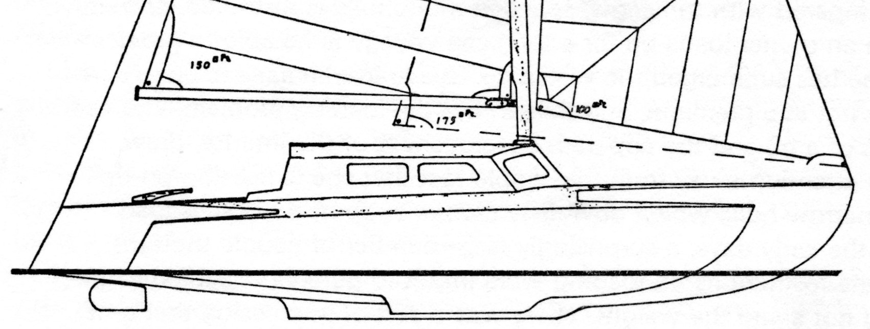
There have been a number of experiments with float forms. John Westell’s Ocean Bird design was very individual. His simple folding-system was adopted by the very successful Danish Dragonfly trimarans. A Derek Kelsall constructed boat FT 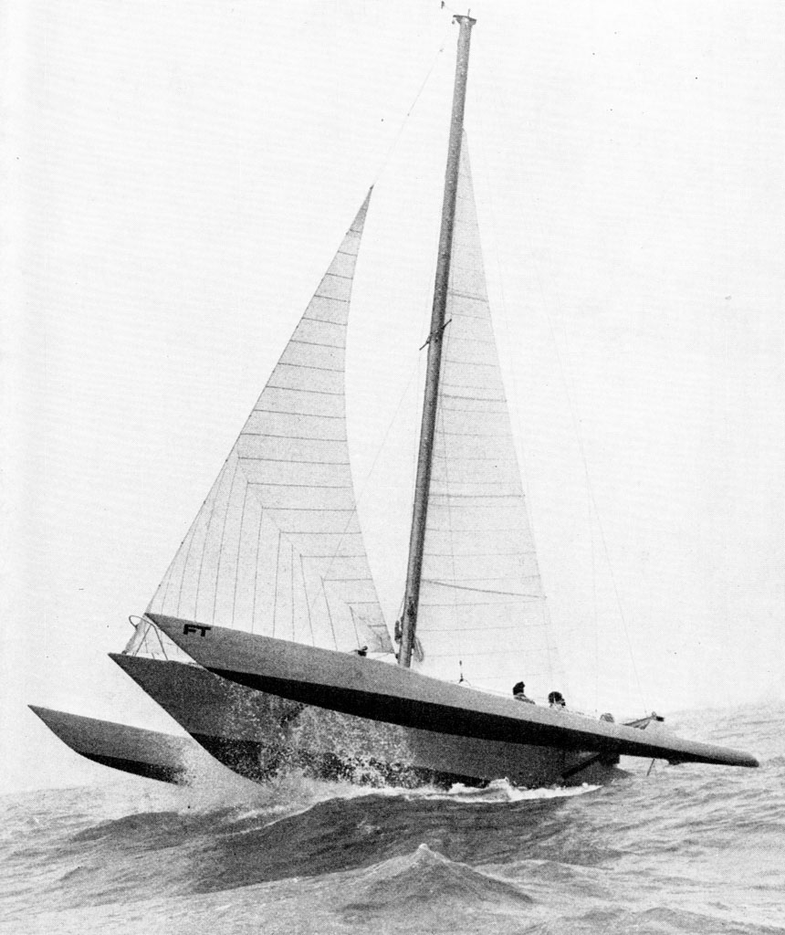 (Financial Times) for David Palmer, investigated very long floats with highly buoyant bows slightly ahead of the mainhull bow. The picture left, shows the extreme floats and raked bow shapes. The boat was an experimental trans-Atlantic racer, to discover what could be gained by maximising a hull form to exploit racing-rule parameters. The mainhull LWL was only 28ft. Much knowledge was gained, especially that the rudder was trying to steer the bow of the float which was set 13ft to one side and 35ft ahead of it. This put a huge load on the rudder. Kelsall said that ‘more was learned from this design than any other, before or since’. In particular he stressed lessons about rotational momentum relating to weight, distances and centres of gravity. There is little need for us to be worried by this, but it demonstrates that the trimaran structure can be a fascinating engineering challenge. The boat did complete the Atlantic crossing.
Amateur builders are sometimes attracted by the idea of adding day-sailing catamaran hulls to the sides of monohull-style craft as 'floats'. This may have some limited success, but it is not the best or safest approach. In trimarans the relative buoyancy and its position in all three hulls needs to be considered in total, almost as a single operational unit.
A friend, experienced at constructing small trimarans by various methods converted Tornado hulls to use as floats for one of his craft. The Tornado is 20ft in length, so the hull size will restrict the overall craft length. The Tornado hulls have a very flat run and insufficient rocker as floats. To modify them he explained that he had to support the hulls, take the decks off and the daggerboards out. He generated the new deck shape on his computer to get fair curves. He forced the hulls to be wider in the middle by pushing the sides out and using ratchet straps. This process lifted the ends to increase the rocker. New bulkheads had to be inserted. He thought that the amount of work involved was hardly justified and it might have been just as quick to use ply/epoxy from scratch, another method that he is very familiar with.
My floats
In general, my floats were based on the successful Derek Kelsall design that I used on Starship. I first saw it on Three Legs of  Mann and recognised it as putting the buoyancy in the right places whilst minimising weight. This float shape was tested to the extreme on Starship (Serial Starship Page 381) when a sustained, hurricane-gust of wind heeled the craft to the limit, whilst blowing out the mainsail and reducing the headsail to ribbons.
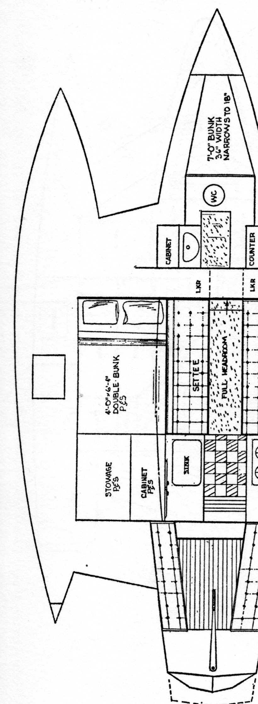
 The basic features of these estuary-cruiser floats are:
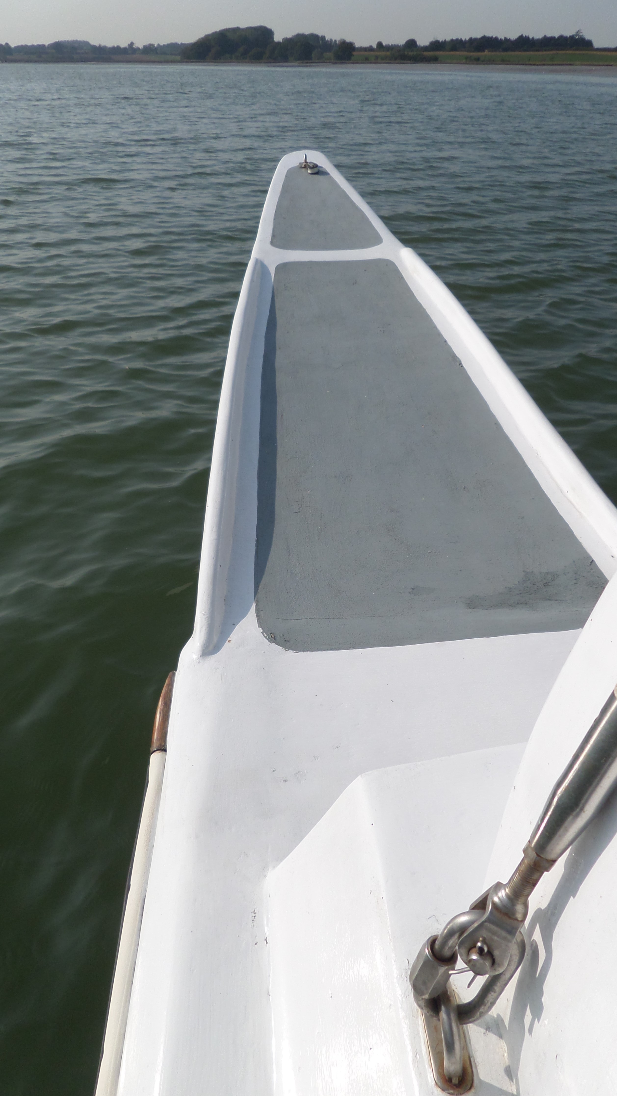
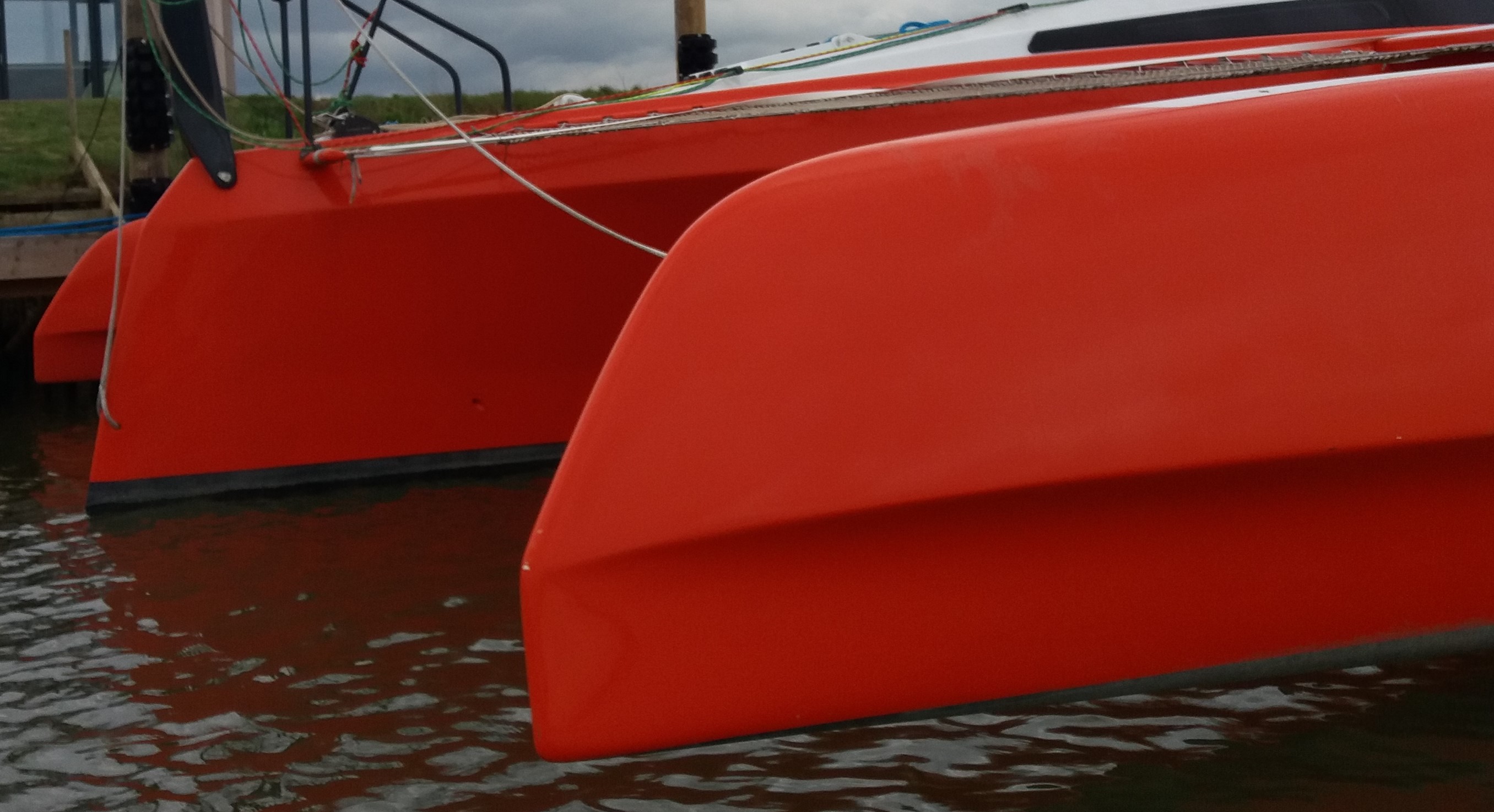
Flat decks. These are not common on racing craft, but in cruising it is essential for the crew to be able to reach all parts of the boat especially sterns and bows, for fending off quays, securing fender-protection for pontoons and other craft, for boarding and possibly, man-overboard recovery. It is important to be able to go to the float bow when picking up or dropping moorings. This is often done on hands and knees. The rails are small raised areas around the bows of the floats for the crew to help locate themselves if they have to go to the bows. They are integrated into the profile of the float so are not immediately apparent. (See picture, right)
Float cross-section. The same shape-rules apply as with the mainhull, except there is an additional factor: modern floats are lifted out of the water surface. In order to get maximum buoyant lift a rounded cross-section uses least whetted surface area, but it is a bit more complicated than that. The bow has to pick up buoyancy, so it flairs outward into 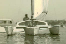 a 'V' from being finely-pointed at the bottom. Further astern, the base of such a round shape presents a flattish area when being dropped onto the water and this means the float can go into the water with a bang in cross seas, whether sailing or on a mooring. The early ‘V’ shape hulls were very much quieter and softer due to their sharper entry. The picture left shows my first 20ft trimaran, based on the Piver 'Nimble' design with 'V' shaped floats. However, 'V' shapes had to heel well over before they picked up sufficient sailing buoyancy, so there was a lack of stiffness. Today, most floats, particularly on commercial-produced craft, have a more pointed ‘U’ shape at the bottom, rather like the inverted top of a church window, to reduce the impact of them entering the water. If solid wing-decks are used the buoyancy of the deck will come into play in heavier seas.
Shape. I do have angled stems on my floats and perhaps if I was to start again, I would have more vertical stems to move more buoyant lift forward. It gives a longer run of the float in the water. However, just as with this issue on the mainhull bow, it is not all cut-and-dried. Manoeuvrability is one of my primary requirements, so my floats are very rockered. Much more so than normal, to assist with quick tacking. Another factor is that putting the bow into the water early will increase lateral resistance at that point and increase the weather helm of the craft when going to windward, which would have to be compensated for elsewhere in the design – moving the main board further backwards for example. The float length/beam ratio should be about 13-1 for this size of craft. Floats should pick up extra buoyancy forwards as they are depressed. I believe in having floats the same length as the mainhull with all three bows in line.
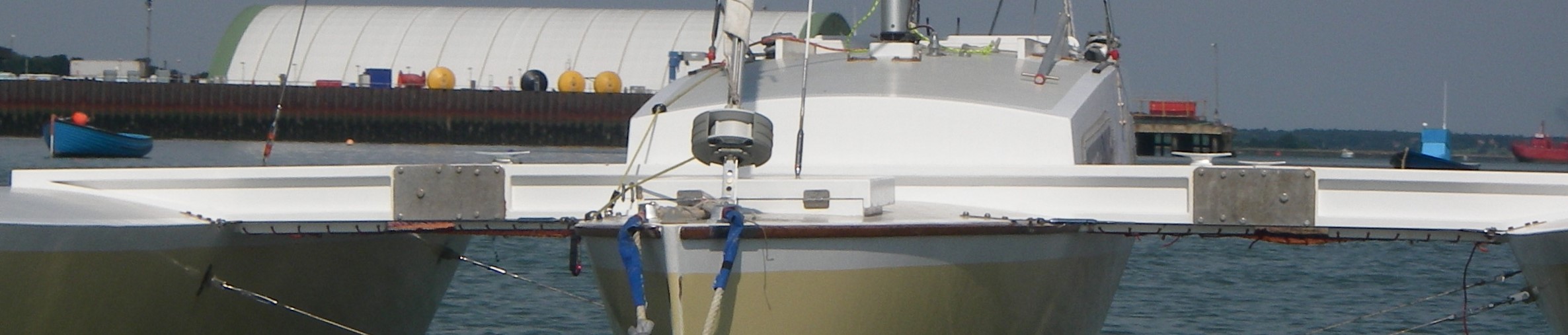
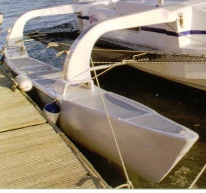 Beam bridges. Both beams are attached to the float on beam bridges (right). It is very important that the attachment of beams can be visible for monitoring and can be accessed easily. On Starship I had the bolt attachments for the forward beams passing through into the inside of the float and access was difficult to the interior parts of these fixings.
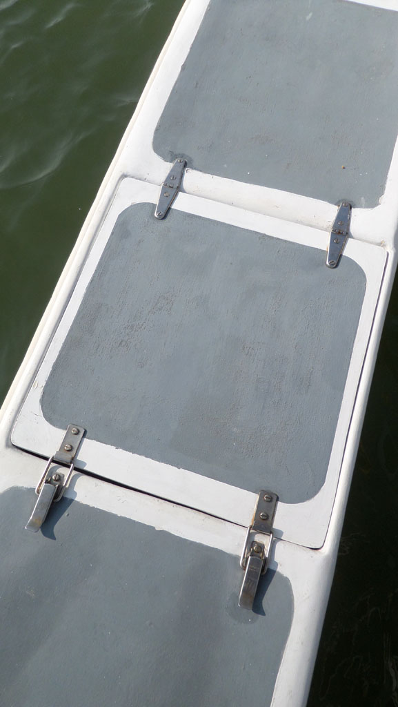
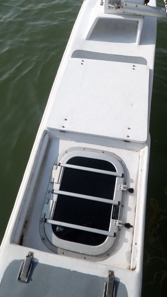 Recessed access hatches. Previously, I had marine hatches like the one in the picture left, on deck, but they were tricky to cross as people did not like to walk on them. On this boat I recessed them down into the float and added a flat, deck flap over them to make a flush deck which was much more successful. The recessed area over the hatch is self-draining on both sides. Having 'raised' hatches with ‘box’ lids is not a good idea as water can be driven into the contact-gap where the lid touches the boat. If hatches are like this, they must have deflectors in front of them to protect them.
Rig attachment. The cap-shrouds are not attached to the floats, so there are no chainplates. They attach by rigging spans to the ends of the beams. More of this later. It allows the floats to be taken off the boat without removing the mast, if this should be necessary and avoids chainplate bolts piercing the floats.
Float Storage. All advice about floats says that they should be kept lightweight for reasons of ‘rotational momentum’, to use Kelsall’s phrase. Basically, keep the weight as central in the boat as possible. It is good advice – BUT – in the estuary-cruising world it is taken as ‘advice’. The floats are too good a storage place to waste and so, they carry all those essential bits of equipment, that separate cruisers from racers. Wet, smelly, awkward or dangerous things, fenders, warps, tender oars, wellie boots, fuel cans, possibly the tender’s outboard find their way in there to free the whole of the mainhull for useable, clean, accommodation space. Bernard Rhodes, mentioned earlier in this section for crossing the Atlantic and the Pacific in his 22ft plywood trimaran Klis, believes in storing equipment in the floats, as this slows down the 'roll-period' of the boat, to use his technical term similar to Kelsall's above. Rhodes says that lying a-hull in big seas needs a high 'transverse moment of inertia'. Having good buoyancy across the boat as the wave hits, helps retain stability. For this reason he feels that catamarans with engines in both hulls have better 'inertia'.and having weight in the floats similarly increases inertia. You can take your choice. Chay Bligh always said, 'Keep sailing- don't lie a-hull.' but to what wind strength is this possible? I took his advice in F10 when crossing the Bristol Channel when bits were being swept off my boat (see Starship book). I have to add that Bernard Rhodes survived a typhoon returning from Japan to New Zealand when the waves were breaking things off his catamaran Flying Carpet. He has huge ocean experience and I have none, so I defer to his experience. This allows me put 'stuff' in my floats up small East Coast rivers.
Protection. There is a plastic rubbing strip running the length of the outside gunwale between the beams. It has teak wooden end caps. The very tip of the back of the float has a wooden protective pad. The rear corners of a trimaran are vulnerable when leaving a harbour wall. If the craft is moving out under motor, the rear inside corner will scrape the wall as the boat turns because the shape of the whole craft is a wide rectangle rotating on a vertical midpoint axis. It is essential to have clearance on this corner before turning sharply out.
 Racing floats. Modern racing floats have turned things upside-down. These bows are on the racing trimaran Freshly Squeezed. They are very fine at the bottom for cutting the water in light weather with minimum drag. They then flair out to produce the buoyant lift for when the craft is harder pressed. The shape reaches as far forward as possible, but the top of the float is curved away to reduce any windage and to aid cutting UPwards through the water should it be depressed below the wave surface. The mast on this craft is heavily angled backwards to produce sail-lift, thus reducing downward pressure on the bow of the lee float. In general cruising it would be tricky for crew to access the float tips on deck. These floats are for speed.
Crossbeams
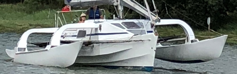
There are many options for crossbeams, but fundamentally they must support the floats at the correct height and in alignment with the mainhull. Keeping the crossbeams clear of the water is recommended. Some forms could contact the water (see below) when the floats are heavily driven in waves. My floats are clear of the water when the boat is at rest. Commercial cruising trimarans may have the floats just touching the water or slightly immersed. Early trimarans had surface-piercing floats and wing decks (see earlier picture above left). This meant that the floats were in the water all of the time, so they produced a very spacious platform, rather like a catamaran. They gave great stability and comfort, but having to steer three hulls around, made them slower to tack and increased the loading on the structure in waves. It was Derek Kelsall who first suggested lifting the floats clear of the water with his ground-breaking Toria design. This radical improvement in trimaran design allowed the boat to tack more easily, as only the mainhull is in the water as the craft goes head-to-wind. It simplifies the stresses. Once the windward float is clear of the water it acts as a counter-balancing weight, trapezing and trying to keep the boat upright. On the previous designs, surface-piercing floats continued to lift the boat on the windward side, contributing to heel whilst that windward float was in the water. Keeping floats clear of the water reduces whetted-surface drag.
 The simplest crossbeams are straight wooden beams, solid or boxes, or combinations of the two. The wooden 'I' beams above (22'-6' Night Heron design by Thomas Firth-Jones) are made to hinge in the centre. This was an old plywood design. The spec for the beams was ¾'' x 5½'' deep plywood, with 1¼'' thick stringers top and bottom. With a straight beam the floats have to be quite deep in order for them to reach the water if the mainhull had high freeboard.
There are a number of instances of metal beams breaking. Both John Westell and David Palmer (mentioned above), had misfortune with metal beams. 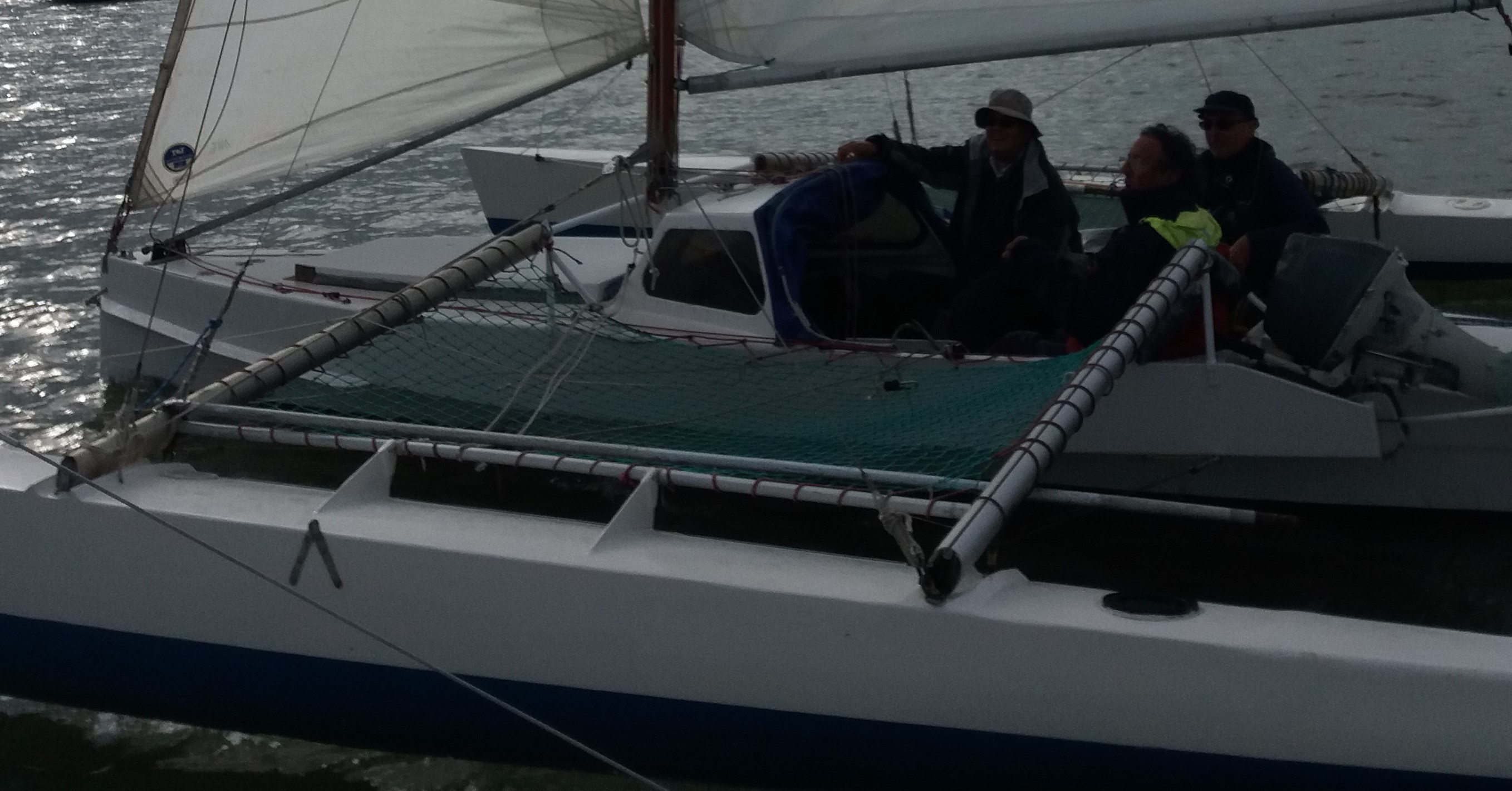 Westell lost a float from Johnwillie and concluded that welds should not be relied upon. David Palmer had cracked beams and engaged in much research through the Wolfson Unit at Southampton University. He thought that metal was more prone to instant failure, but composites fail more gradually, giving warning. Morris Arthur designer of the Round Britain racing proa Anglia Pipedream agreed, saying, ‘Failure should be in easy stages.’
Metal tube beams On my craft I tried to avoid fixing the beams through the mainhull or float hulls. Starship had aluminium beams that crossed inside the hull and then had hinged, galvanised-steel ‘A’ frames attached to them externally. They were never a problem, but they were heavy. The lower component of any ‘A’ (the A is turned on its side) frame will come closer to the water. I was interested to see that Starship returning from a West Country cruise, in a 24hr day, sailed from Start Point in Devon, to Dover, well over 200 miles, but in so doing stripped all the paint off the front edges of her beams. The beams had all the primers and then five coats of 2-pot paint on them – gone in 24 hours. The lower the beams, the greater the abrasive action and impact of the water. To provide minimum resistance, an upper wood/metal/composite beam can be tied down using a rigging wire ‘water-stay’. I thought that the attachment of the stay low on the hull could be a possible source of leaks with the possibility of fouling something at some point. I have friends who say that they have never had problems with them. Dick Newick’s very successful, racing Val class used this system. The rigging stay carries a major tension load as the float is submerged and pushing upwards, but the upper beam alone carries the weight of the float as it trapezes out of the water when the stay is effectively not functioning except to carry rigging load.
 I opted for a high, composite beam, curving down to attach to beam bridges. The 7" square, box beams plus fairings are strong enough alone to carry the stresses imposed by the float. They carry the load right across the top of the mainhull without the internal intrusion of any beam structure that could reduce internal space. Fairings must be very strong. They cannot be 'additions' as they will soon be ripped off as was experienced with FT and other earlier craft (see below).
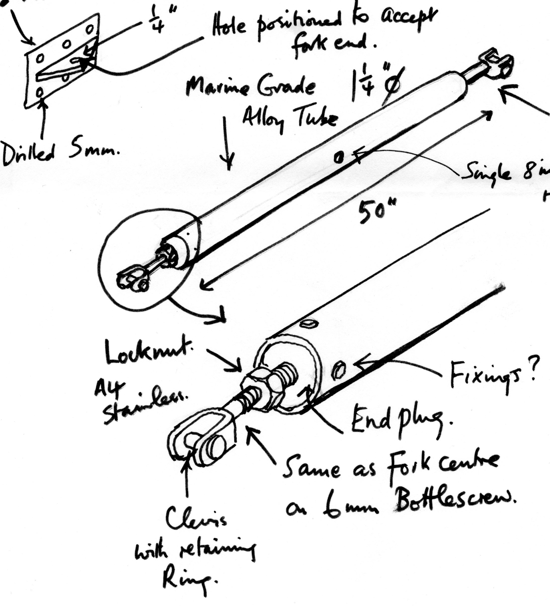
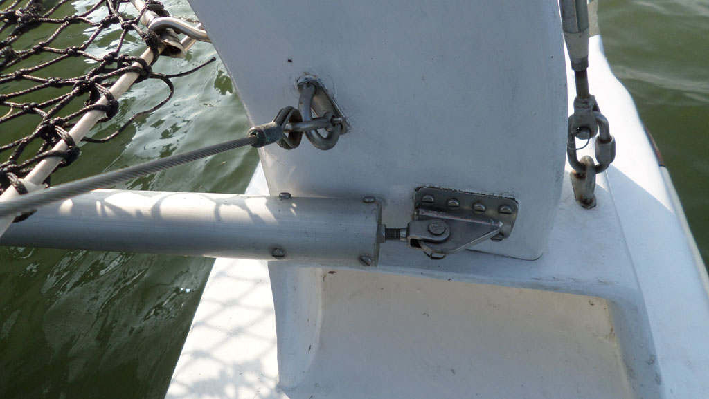
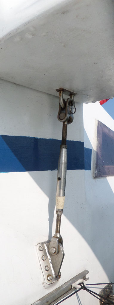
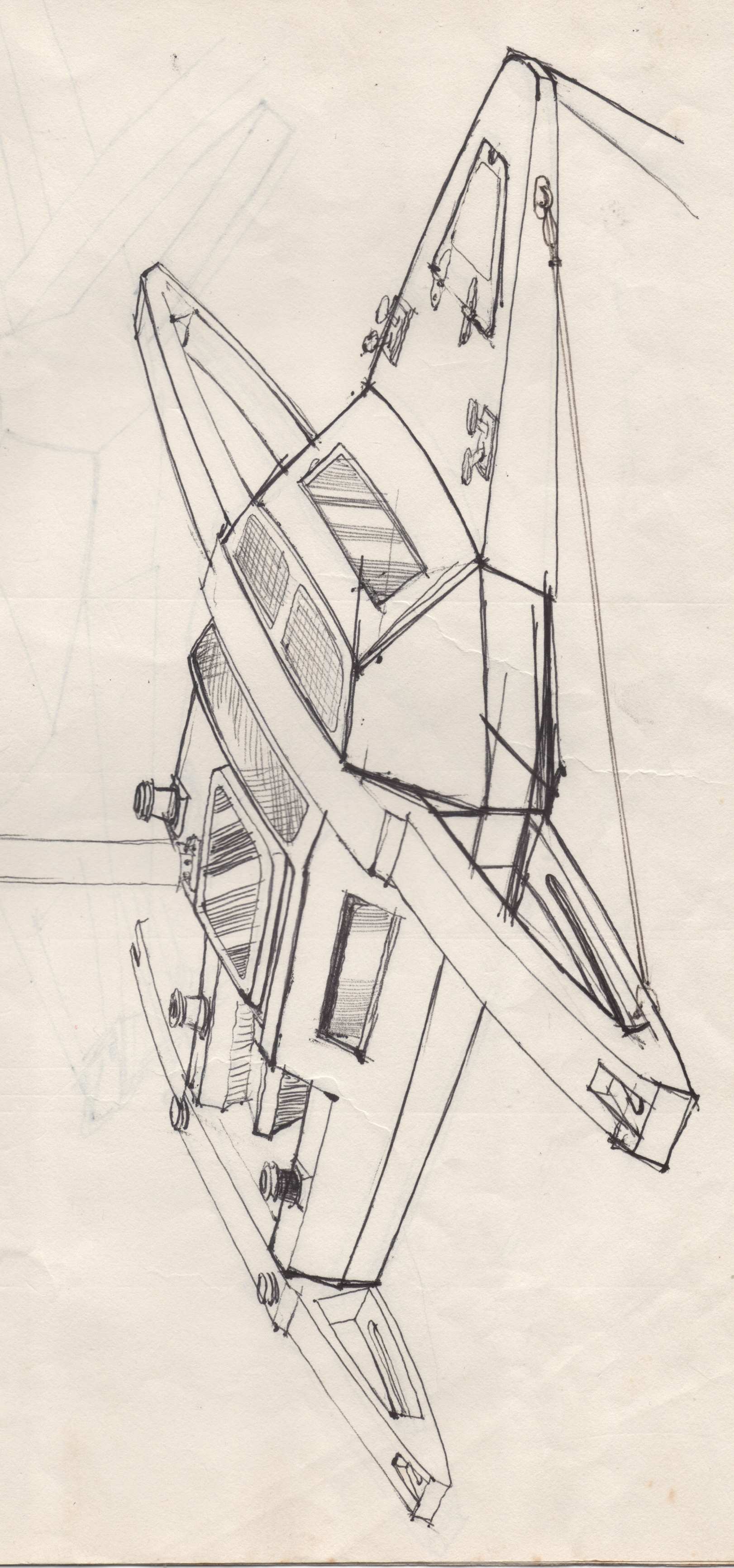
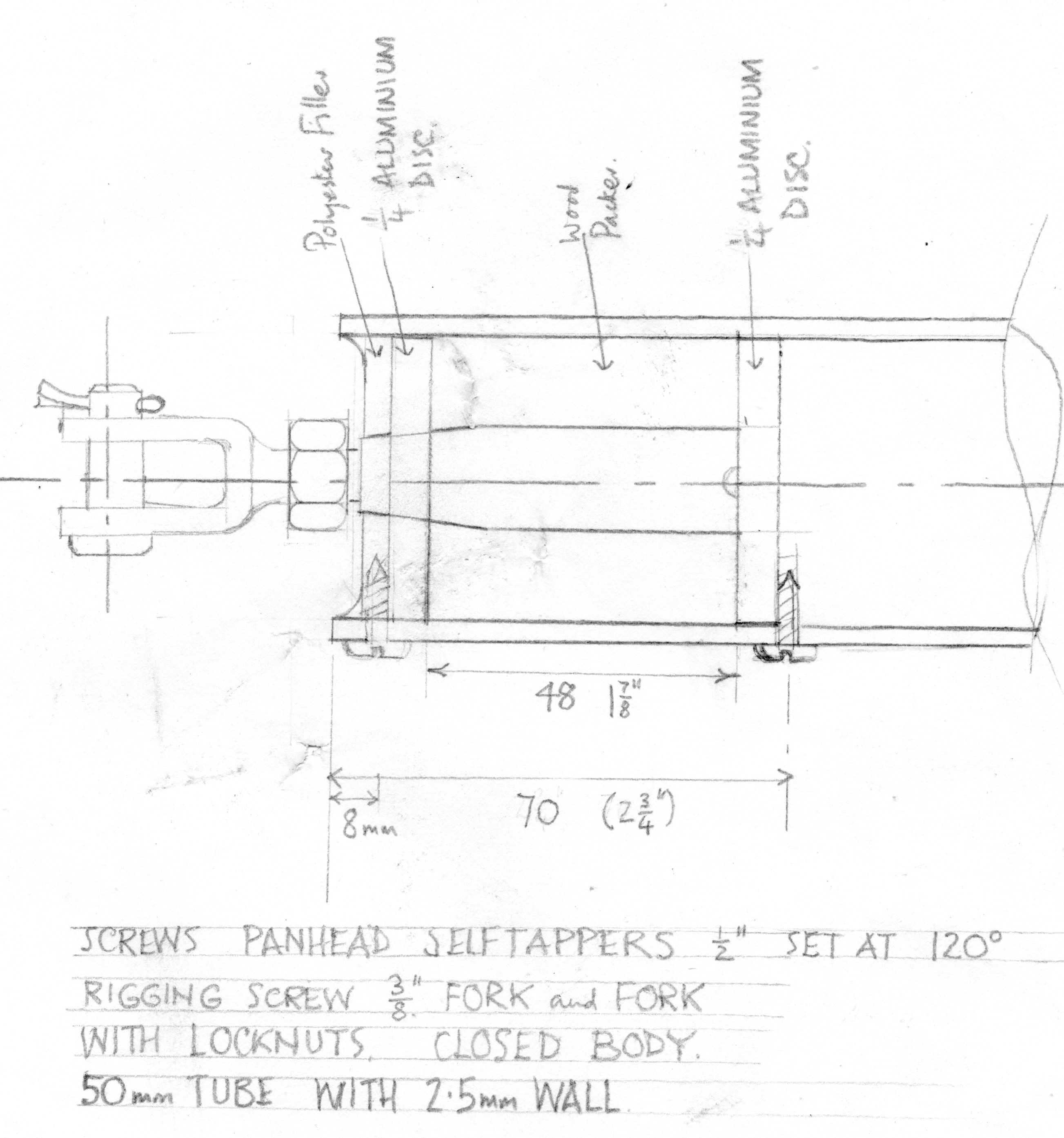 The lower, horizontal component of this beam system is an aluminium tube in tension, to assist in taking rigging loads, but also to provide a supporting point for walkways down either side of the mainhull that substitute for side-deck. To secure these beams in place they needed to be attached and then tensioned by pulling the ends in. My original sketches (left) showed what I thought might be needed. I came to realise that I wanted something like a 1.5m long rigging screw. I hit on the idea of sawing a rigging screw in half and attaching the parts to the ends of an aluminium tube (pencil sketch right). The attachment uses a pair of close-fitting aluminium discs inside the tube secured by three self-tapping screws at 120° outside the discs. The screws are in shear and have proved to be easily strong enough to take the load. The outside ends (see picture right below) encapsulates the screws in resin putty which protects them. I thought that I might need a central hole in the tube for a tommy bar, but this was not needed, so they are sealed and saved from internal corrosion. Their clevis pins are inserted both ends and then the tubes turned to tension them. Locking nuts fix them both ends. The tubes are one of the very satisfying experimental ideas that worked first time.
 Beams are fundamentally boxes, but they can have fairings to deflect the water. Fairing have been found to take a huge pounding and cannot be flimsy additions as they will always fail. I included the fairing as part of my beam structure. The beams are broader and deeper where they attach to the hulls and become more slender outboard, then increase in size to provide a broad base where they sit on the beam bridges. Their attachments will be dealt with below, but they have a projecting ‘tenon’ that locates into a ‘mortice’ cut into the top of the beam bridge.
Attaching Beams
 The boat was always designed to be demountable, not folding. The concept was not to go for a rapid assembly, but to put the components together securely. I saw an advert in PBO for Protex Fasteners (see left) which illustrated some over-centre toggle clamps which were made of stainless steel. They seemed ideal and have proven to be so. They are still available today. The crossbeams have a recess on the underside where they cross the mainhull, so that when they drop into place, they locate on either side of the hull. The Protex latches on this crossbeam then lock them down. These are adjustable by screwing the solid, cylindrical toggle end, so their gripping power can be maximised. Rubber pads are inserted under the ends of the recess as 'gaskets' to ease the mating-surface compression on the mainhull. The floats are located by slotting the athwartship tenon into the mortice on the beam bridge and the inside face is locked with more Protexs. Any over-centre device exerts peak power just before the lever is moved over to the locking point. It is that max-power-point-passed that holds the lever closed. I did wonder about this as the clamp is not at max-power in use. I also wondered if it could be possible to snag a line under the lever to accidentally release it. I saw that Derek Kelsall was using rigging screws to secure floats on a small trimaran. When I asked him about it he just replied,’Well, they are used to hold the mast up.’ Basically, this meant that he had confidence in them, so I used them too. They give adjustable
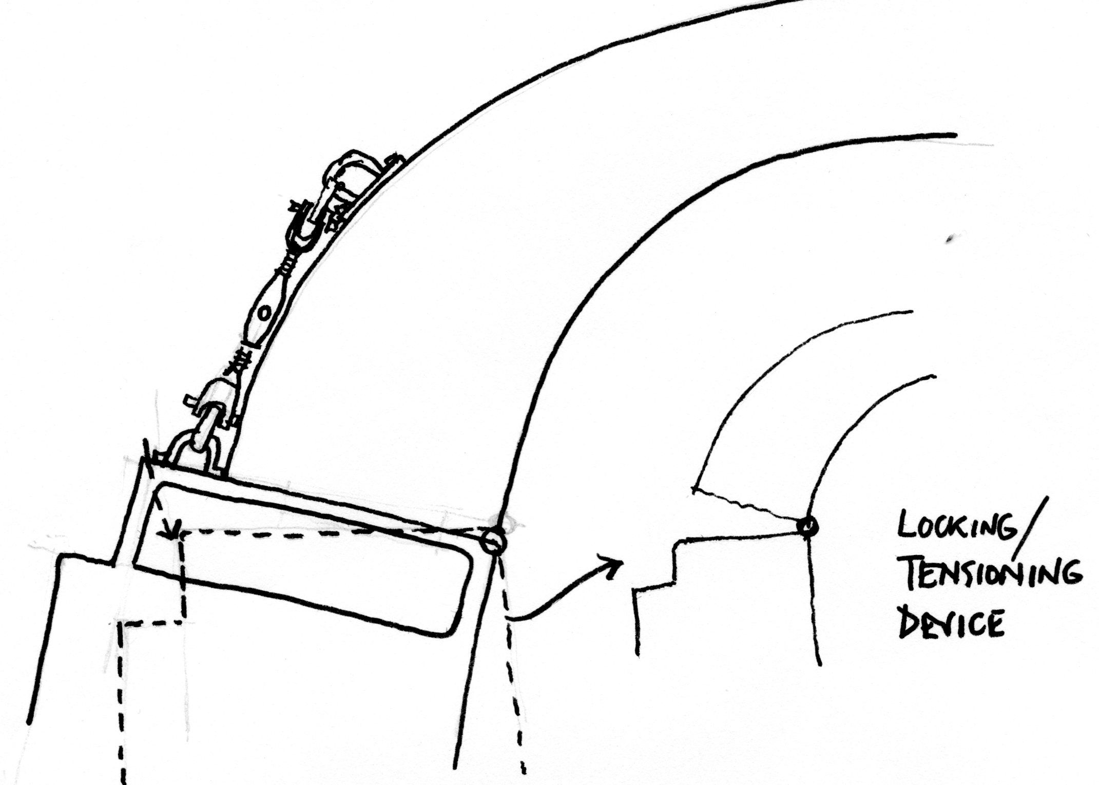
 leverage for locking the floats to the beams by not being over-centre. I also used them to secure the aft beams to the mainhull (above right).
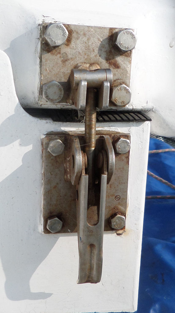
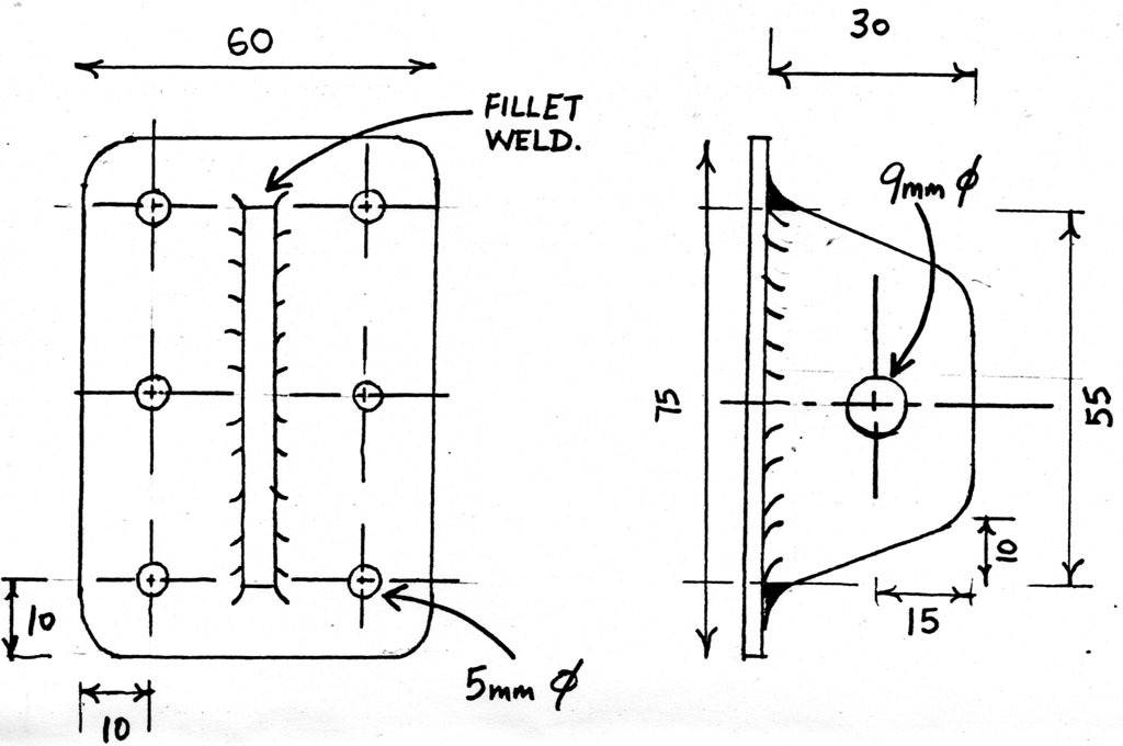
I have included some drawings here from my sketches at the time. I needed some firm attachment fixing-points and made a drawing (left) to send to suppliers of the fitting I thought would be needed. By return, I received a drawing from a spar maker showing an almost exact copy with similar dimensions for a standard, inner-forestay, mast fitting, so I was able to use them instead of having to have them specially fabricated. They have backing plates. My rigging screw attachment on the outside of the beam is very similar to my original sketch. I used Quick-links instead of shackles as part of the assembly and they were the only components to fail. After several seasons they both sheared off at the starting point of their thread, whilst being released for disassembly. I increased the size of them. If they are strained by imposing load before being fully screwed together, the thread will become misaligned. It will then be difficult to engage the thread properly. The nuts must be fully locked closed before taking the load.
Rigging the beams 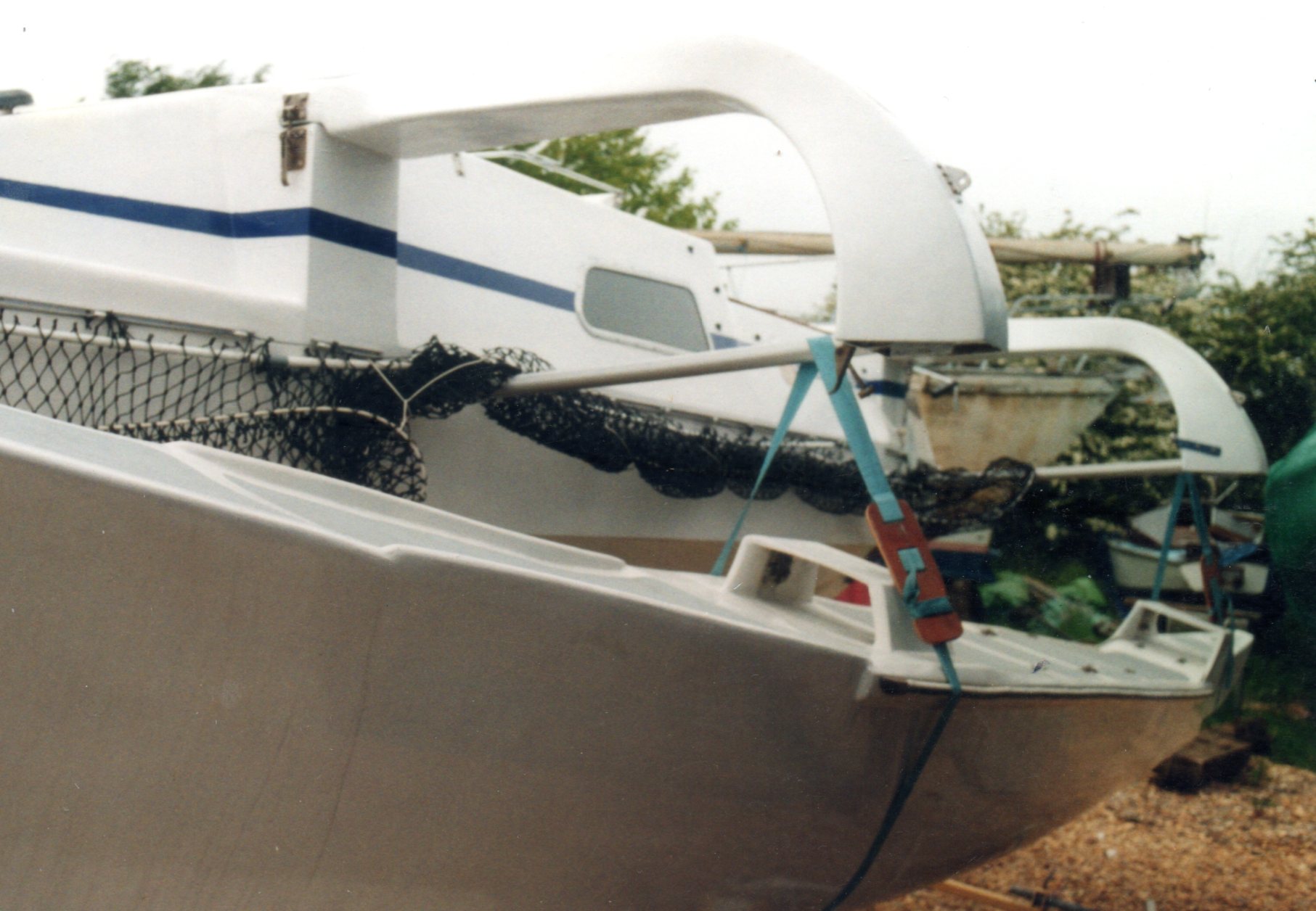
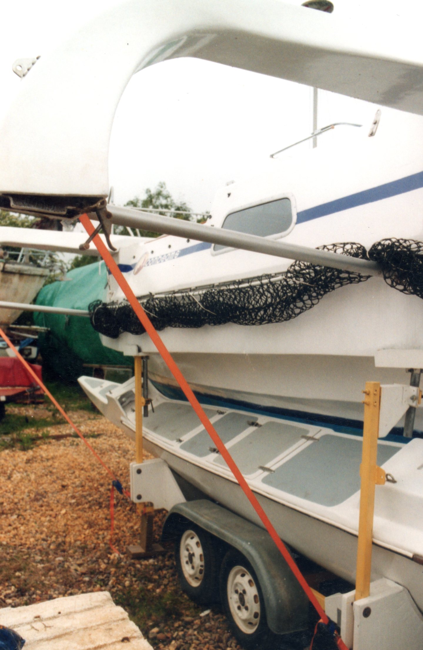 I had many iseas about how to attach the beams which I worked through on paper. I was influenced by the idea of trying to slide the floats along the beam in order to rig them, then sliding them back to stow them. The boats does have this facility. To move the floats up and down for assembly, they are suspended with webbing straps (blue) from the aluminium poles that are part of the crossbeam structure. The trailer support-arms are lowered during the movement and then lifted again to support the mainhull. A webbing ratchet strap (orange) linking crossbeam to trailer (see right) can be applied to the opposite side of the boat to help to secure it in an upright position during the movements.
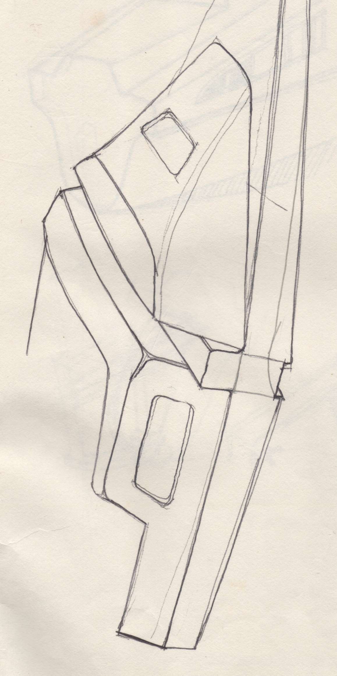
Below are a couple of sketch concepts for beam seating and housing. The left sketch still has the mast in the aft position.
Nets
Trimarans can have solid wing-decks and most of the early cruising ones did, as they provide such a large working area on deck. Plywood wing-decks were susceptible to damage from being pounded from below in big seas. This was another design feature that caused the loss of some craft. Folding trimarans now have a fine mesh cloth that allows the water to pass through it. I like to see 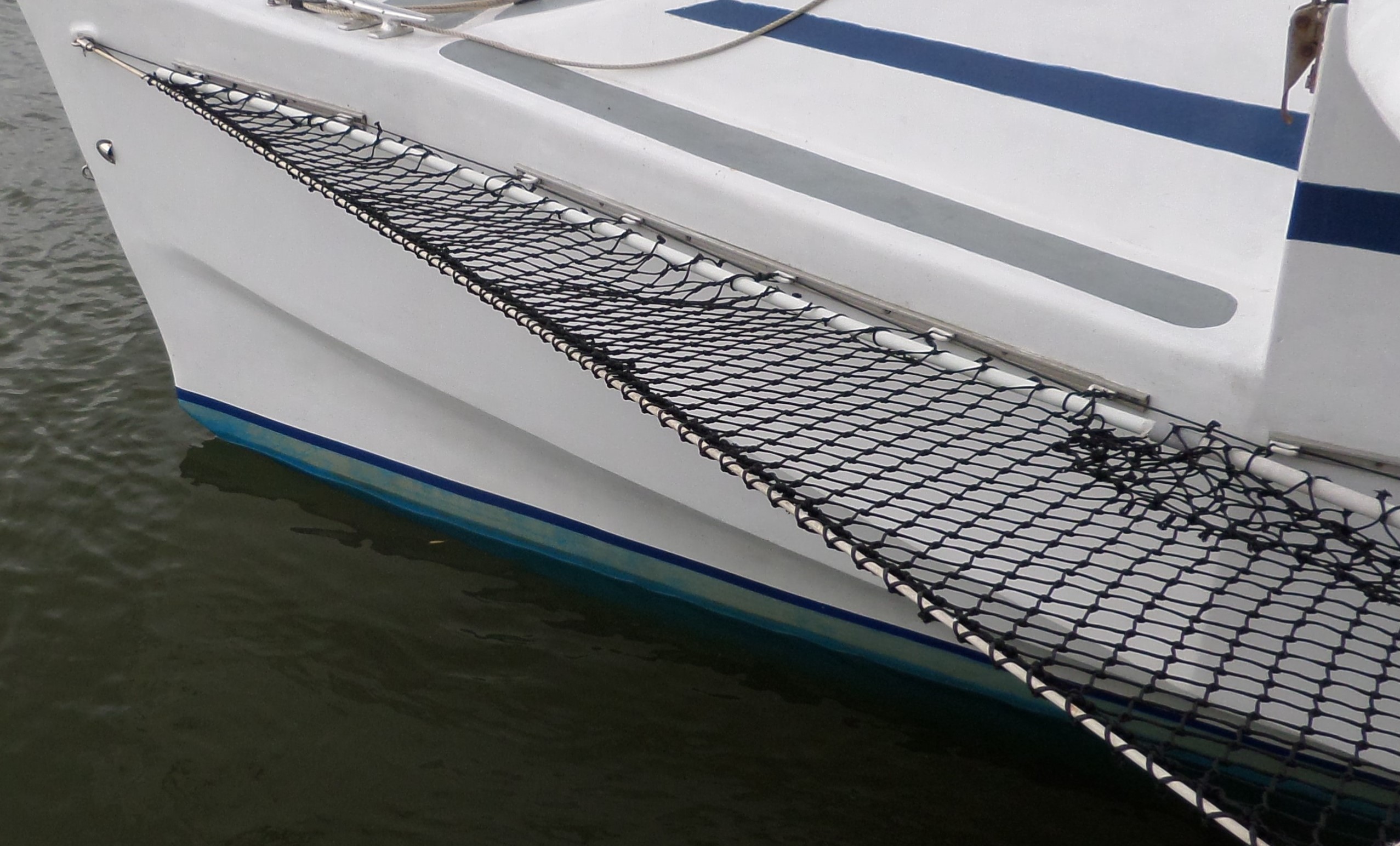
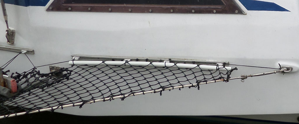 the floats working in the water. I am also aware of the windage and so I prefer to use fishing net, which is relatively cheap, but enormously strong and durable. The big problem with nets or ‘trampolines’, as mesh cloth ones are called, is securing them to the hulls. Having many individual metal loops bolted to the boat is time consuming, expensive and every bolt need special attention. I opted for sail tracks through-bolted to a wooden rail inside the boat. The sail slides can be positioned anywhere along the lengths of track. To attach the hull to the netting, I ran lengths of plastic waste pipe through the edge of the mesh. I then lashed the plastic pipe to the sail slides with the same kind of cord that the netting is made from.
The outer edge of the netting has a plastic-covered rigging wire that is attached to the front corner of the mainhull bow on each side. It runs out to the ends of the beams and returns to the mainhull at the rear corner, where there is a tensioning rigging screw. The whole of the area within the boundary of the wire has netting. It is particularly important for working the ground tackle at the bow which is quite fine on deck. The tensioning to the mainhull by the continuous lashing between pipe and sail slide is 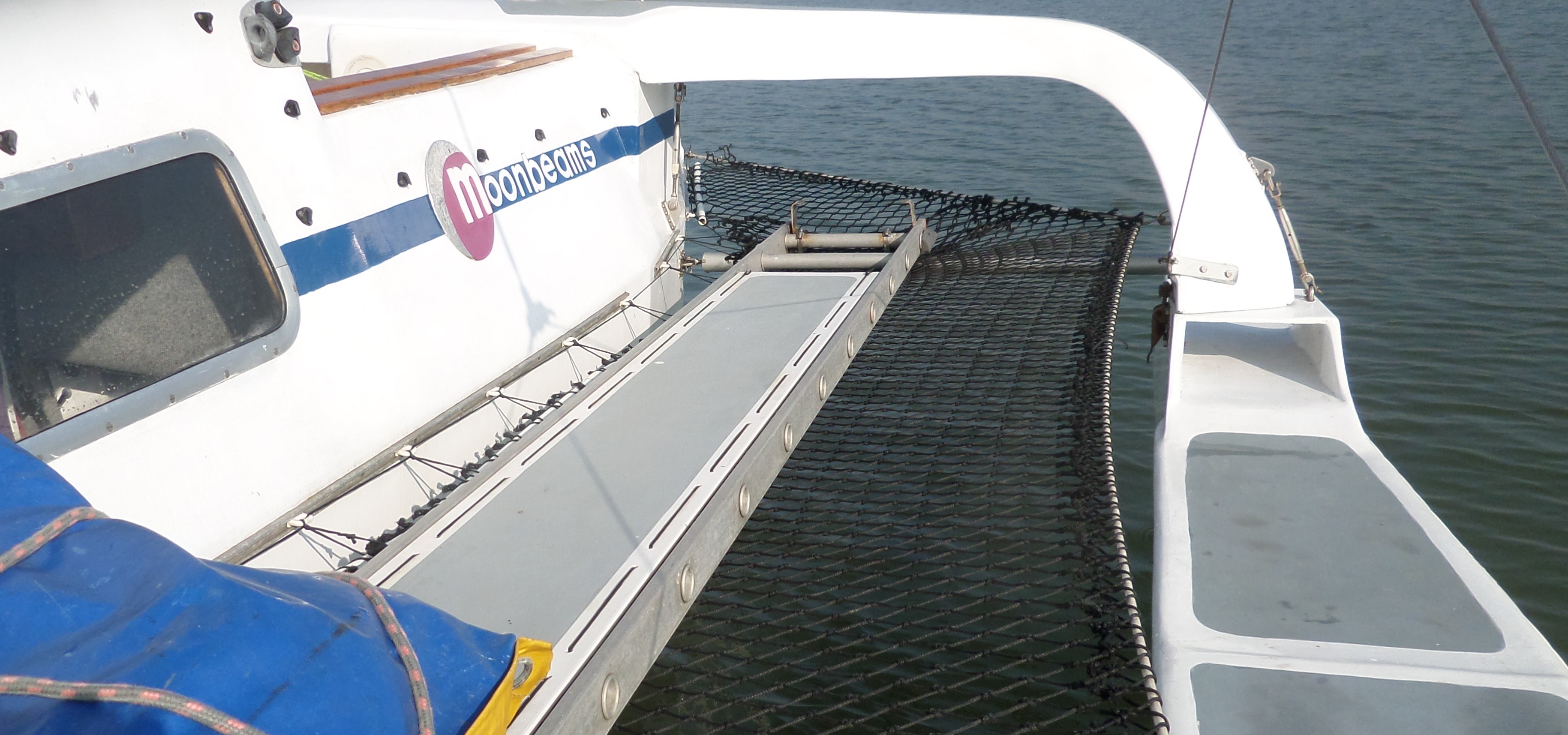 retied/re-tensioned each season, so that it can be closely inspected. Although it is a continuous lashing it is locked off at each sail slide, so that if one part should fail, it will not run through to adjacent lashings. This is done in memory of Rob James, a very experienced ocean racer, who was lost from his own craft doing a routine delivery, when the lashing broke, so he fell into the sea and his crew was unable to recover him in time to save his life.
The tensioned, perimeter, rigging wire has a compression effect on the beams, helping to lock the whole beam structure in place and giving 'supporting pressure' to the lower aluminium component of the cross beam.The two are 'belt and braces'.
Walkways
As mentioned in the section relating to the mainhull, to gain the maximum internal volume for accommodation, there are no shaped sidedecks on the mainhull. To go forward there are walkways from crossbeam to crossbeam outside of the hull. I initially thought that they could be made from tensioned trampoline-like material above the nets, but I found it impossible to get sufficient tension. This meant solid walkways, 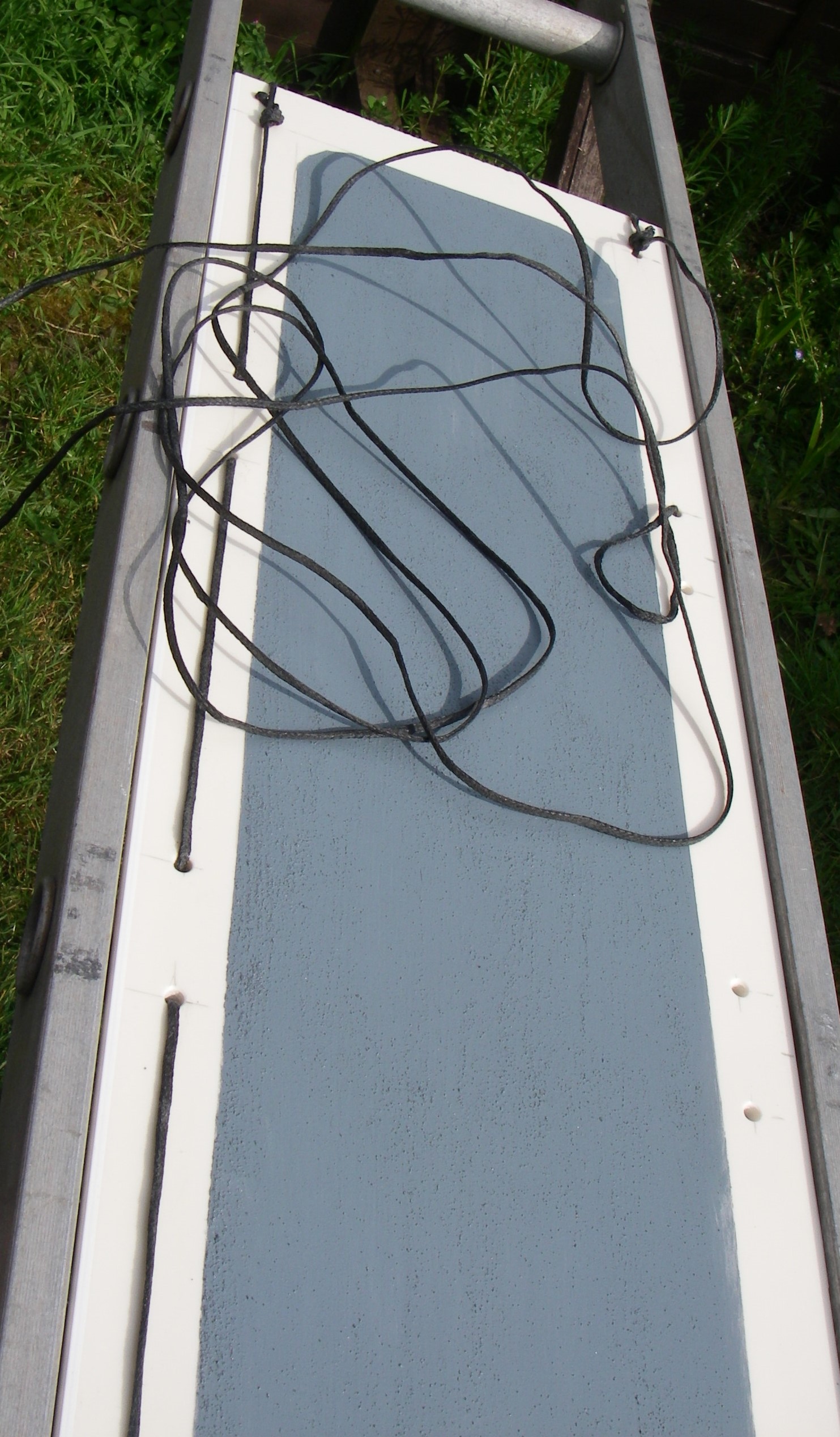 which could be heavy. I began by defining the support structure needed and then realised that I was inventing something that looked like a ladder, so I found aluminium ladders which were as lightweight and as strong as any alternative. One ladder is slightly narrower than the other so that they can be locked together to be extended. I left the brackets that allow this on them, so that they could still be used as ladders if their walk-on deck boards were removed.
To produce the solid walk-on surface, I began with 6mm plywood, then 9mm plywood, but they soon failed under the extreme marine environment and UV light. I then used 9mm solid-plastic soffit board, which proved to be much more durable and relatively lightweight. Eventually, I used the UV resistant upper surface of the plastic board, with a 6mm plywood board bolted to its underside for rigidity between rungs. To fix them to the ladder rungs a series of holes were drilled through the boards on either side of each rung and then a continuous lashing used lengthwise, sewing down through the board and around each rung. The top surface of the 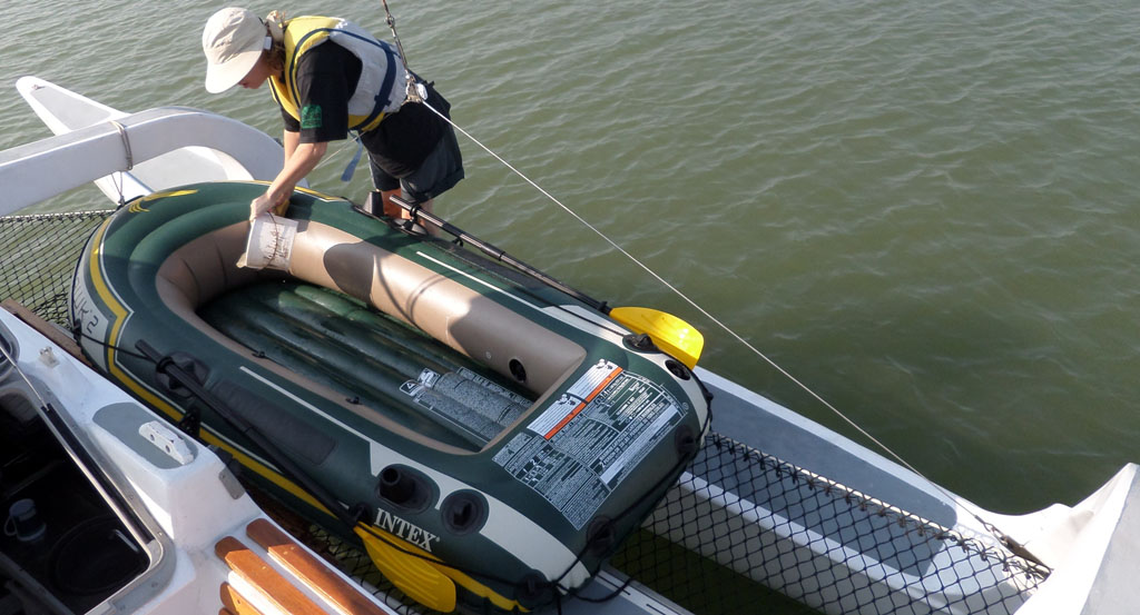 boards have non-slip paint applied in the same way as the decks. Exposed ladder rungs at each end are secured to the aluminium-tube lower crossbeams with stainless-steel, Jubilee or worm-gear clips.
Going forwards on the boat involves stepping outside the mainhull onto the walkways between the beams. This feels very safe as there is netting below and outboard of the walkway, with the float beyond that. I thought that a line from forward beam to rear beam outboard of the walkway could be used as a ‘handrail’ for security, but this is not necessary. The topmast-shroud span (see Rig and this picture) acts in this way. The nets provide wide side 'decks' so we can use them for loading and unloading from the shore tender and for working on our inflatable tenders. This photographed tender is for quick trips when the shore is close. It can be stored in a float. We carry a much more substantial tender with outboard, bagged and secured on the opposite side. We can sail with the inflated tender rigged with outboard on deck if we wish and do not have to tow it astern with its attendant drag and risk of loss. This is a huge advantage compare with the restricted deck space of the monohull form which has always struggled to find working space for the tender.
When viewed from on deck the boat appears to be broad to people newly arriving on board. I can explain that this area might be impressive, but the mainhull is actually only 3ft wide on the waterline which is significant when sailing in areas of small mooring buoys that can pass below our windward side.