GRP Flat Table Boatbuilding 9
Panel Making
With all the preparations in place this is how a panel is made.
Recap to this point
- The mould table should be at a reasonable working temperature as it is not really possible to apply heat to the external resin layer on the table after the foam has been applied.
- Release wax has been applied and the table polished
- The foam has been cut to shape and checked
- The glass has been cut to shape and arranged in the correct order for application
- The foam has been punctured to release any trapped air
- A 50mm (2ins) strip has been cut from the foam edges where the panel is to be joined to another panel
Working Time
The time taken for the next series of steps will vary according to the number of persons involved, the area being worked and the number of layers of glass being applied. It is reasonable to expect that at normal working speed, one, to one and a half hours will be needed to lay and consolidate the glass, then apply the bag. The vacuum will run for about 2 hours, so a total time of about 4 hours will be needed. Other work can be covered during the vacuum bagging period – it is NOT safe to leave the vacuum running unattended, it must be checked periodically to ensure that it is not overheating and that the pipe has not become dislodged, releasing the vacuum from the bag. Listening to the sound of the cleaner allows continuous monitoring.
Making the joint rebate
Place the foam on the table complete with its edging strips, with OUTSIDE down and draw around it with a chinagraph/felt tip pen, leaving a wide margin of table top outside this perimeter line for attaching the vacuum bag. Now remove foam edgings.
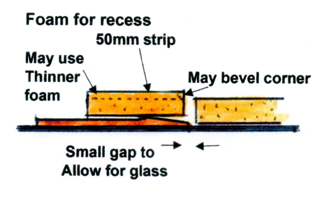 On any edge requiring a joining rebate, place a hardboard strip so that the outer pencil line is over the perimeter line just drawn, or slightly outside it. Being guided by the foam still on the table helps.This means that 25mm+ (1"+) of the hardboard will be outside of the final panel size. The hardboard can be ‘tacked’ in place with masking tape from the table onto the outer 25mm of hardboard. When the foam is later placed inside the hardboard defined area it must not be a tight or exact fit, because some layers of glass that make up the outer skin of the boat will have been put in place below it. The bottom corner of the foam panel close to the feather edge needs to allow some extra space for the laminate to curve up onto the hardboard to make the rebate/recess. Remove the foam panel from the table. Carefully apply parcel tape to cover the hardboard from the outer pencil line across the inside taper and down onto the table. Avoid creases or air bubbles and press it firmly into the junction of the feather edge and table to avoid any air bubbles forming at this point. Release wax it.
Using polyester resin
Following only a little experience with polyester resin the average back-garden boatbuilder will appreciate the link between temperature and setting times. The ideal situation would be to have temperature control and always strictly measure precise amounts of catalyst for any given amount of resin. Honest amateurs will admit that in the afternoon on a very hot day – just to get a reasonable working time, the amount of catalyst required will be less than working in the cool of the evening when a faster setting is needed, before the cold night air stops working. The amount of catalyst used will govern setting time. Working in the direct heat of the sun is not a good idea. Possibly the best solution is to be able to work a laminate correctly catalysed, in reasonably cool conditions and then move it to a warmer location. Alternatively, putting up shades, laying-up and then removing the shades works well. It is not always necessary to heat a table if temperature conditions can be arranged to be correct. I cannot know every construction situation and local knowledge must be applied by the organiser of each project.
Gel Coat
 The gel coat is applied to the area inside the feathered edge of the recess strips. This will become the smooth outside surface of the craft. The edge recess is not gel coated. It must remain ‘raw’ fibreglass, so that the subsequent laminating across the joint will bond to it. The gel coat is applied with a soft roller and must be allowed to commence the setting process. It is possible that some gentle heat can be applied beneath the lid to encourage this. Arrange timing of about 30 minutes to be setting. It is common practice not to colour gel coat so that the quality of the laminate can be visible to be checked.
Foam and priming resin
The styrene, which gives the resin its distinctive smell, can penetrate PVC foam. When it does so, it can soften the foam. If a small test piece is left overnight with un-catalysed resin on it, the next morning it will have the consistence of soft white bread. It will be weak and pliable. In a normal construction the catalysed resin will set, thus stopping the release of the styrene into the foam. The foam is only slightly softened, which is beneficial to the bonding of the foam to the glass.
Whilst the gel coat is setting, lay the foam on a flat surface away from the table with OUTSIDE upwards and paint a generous layer of catalysed resin all over this outside surface. The foam has thousands of tiny cells and each is a potential air trap where little bubbles will form. If a glass layer was immediately applied, the bubbles would be trapped. By coating the foam with resin at this stage the bubbles will float to the surface and be released, so that it will provide increased adhesion. One thing that must NOT happen is for the resin to set before the foam is applied to the glass as it would stiffen the foam and resist the air bag pressure. The glass still has to be applied, so timing the mix becomes important. The edging strips also need treating on the outside face.
External glass
Paint the lay-up resin onto the inner face of the gel coat. Hopefully it has been protected, for any dust can only be removed with a vacuum cleaner as the gel will be tacky.
Lay-up the first glass layer. All projects will be different and the materials suppliers or designer will have recommended a specification. Let us say that a layer of CSM is applied to the gel coat as a ‘gasket’, to be followed by two layers of UDWR (see Chapter 3) one longitudinally and the other transversally. There is no need to overlap the cloths, they should be laid side-by-side. The glass will run 50mm (2ins) across the joint rebate up to the perimeter, leaving a short strip beyond the pencil line without glass. The glass should be rolled down to exclude air.
Foam
The resin-primed foam now needs a second small quantity of resin to be applied. Spread it smoothly all over, brushing or rolling it in thoroughly until the foam has an even wet appearance everywhere. This removes surface bubbles and is the ‘glue’ that will need to have gelled in about 1½ hours when mixed with the resin already on the foam. Put the foam in place on the wet glass laminate on the table. Slight movement on the glass is not a bad thing as it helps to force down the imperfections of the weave. The primed edging strips can be positioned and held in place with masking-tape tabs. They will project slightly, but later, once bonded to their glass, they can be reduced in thickness, or tapered, after the removal of the vacuum bag.
Vacuum Bag
Apply the sheet polythene over the whole assembly. Generally, it should be about 50mm (2ins) smaller than the size of the table. If only part of the table is being used the polythene can be folded to an appropriate size. It can also be extended by taping on extra sections. The extraction pipe fitting can be roughly central. To help the air to find its way towards the extraction point it is possible to lay lengths of small rope or tube across the top of the foam to create channels from the furthest corners towards the extraction point. Air will also run out through naturally formed creases in the polythene or gaps where the edges of the foam form channels. The bag is taped down to the table all around its edges with 50mm (2ins) masking tape.
Vacuum Cleaner
The cleaner has all dust collection and filtration devices removed.
The motor only sucks unrestricted clean air.
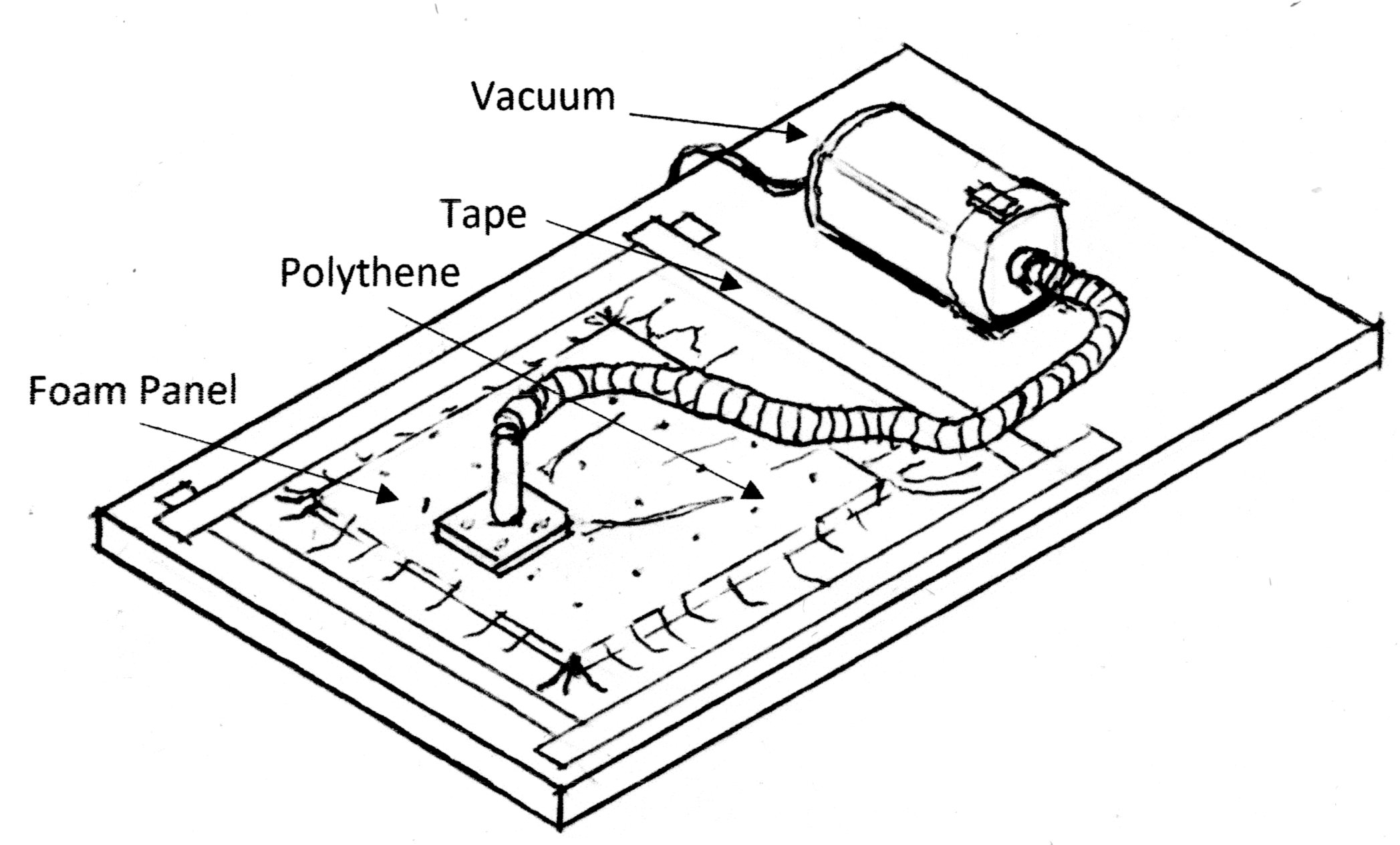 Apply the vacuum cleaner to the extraction pipe and begin to remove the air. Stop and push bubbles towards the centre if needed. Control is exerted by lifting and lowering the cleaner pipe. The machine will only have to finally extract air forcibly for a few seconds and then the rising note of the motor betrays the fact that no further air is passing through it. It will overheat if left like this and become a fire hazard, so air must be allowed to pass through it unhindered. Withdraw the tube from the extraction pipe, but keep it in contact and listen to the note of the motor. The tube will be dislodged, but not completely removed. It is wedged in the opening so that air is not entering the bag's extraction tube, but is mainly being sucked in from outside to cool the cleaner. The noise of the cleaner must indicate that it is now running normally. Air will not bleed into the bag due to the atmospheric pressure keeping it flat. The air has to contend with the established force already flattening the bag. Providing an outward movement of air can be maintained in the pipe, no air can enter the bag. The machine will be quite happy, providing the cooling air continues to flow through it.
Checking
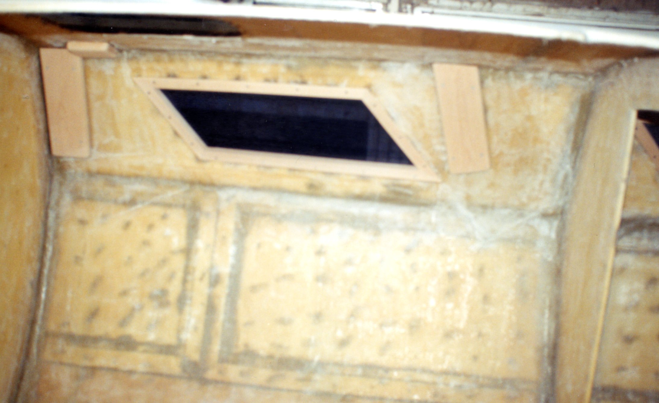 When the bag is flattened and the cleaner running normally, checks must be made around the perimeter of the bag for leaks. They will show if any area does not flatten or appears ‘soft’. They can also be heard hissing above the noise of the vacuum cleaner if an ear is close to them. They can be sealed immediately by applying extra masking tape. Any small hole in the bag can be repaired in the same way. Right. Hull interior showing joints. Filled holes do not show on the outside (see bulkheads to left and right).
The pressure will squeeze surplus resin up the holes through the foam and it will appear as darker areas when seen through the polythene. The resin wrinkles the polythene and these concentrations will eventually become hard blobs which will need cutting back if they are allowed to set. It helps, therefore, to apply localised pressure of a finger on the resin to smear it out on the top surface of the foam by rubbing it through the polythene whilst it is still soft. It is a good idea to leave a few scattered blobs, because they indicate the setting state of the resin. Rub them back at about an hour and then, at 15minute intervals. After 1½ hours they should be distinctly harder.
After bagging
After 2 hours switch off and leave everything as it is, if possible. It should remain like this, preferably for 24 hours. Continue to apply heat under the lid if needed. The longer the panel can be left undisturbed the better. What happens next will depend on the eventual use of the panel.
One side. A panel glassed on only one side (externally) will still have a degree of flexibility and this may be required if it is to eventually take up a curved shape.
If a panel is removed from the table at this stage it must be stored absolutely flat, for it is still at the ‘green’ stage and it will be distorted by uneven surfaces. Curing the panel will depend on temperature and this should born in mind before doing anything ‘major’ with it.
It is possible to make an assembly of all one-side panels and then to apply the glass laminate to the whole of the interior of the assembly as a single continuous process. Whole hull shells could be made like this or part assemblies such as the cockpit. It is the most economical way to make a complex assembly.
Two sides. If a panel is to be made rigid, then it’s upper surface also will need glassing, so it remains on the table. This work can be done as part of the continuous process of panel making, as it is not necessary to wait for further curing once the bag has been removed. The foam surface has to be checked where resin has come up through air holes to ensure it is soft enough or not projecting. If it has hardened it will need cutting back. The raised edges of the foam over joint recesses also has be cut away to make a smooth transition. This is done with the grinderette. Some filler may be required. Glass has to be prepared. Vacuum clean the whole surface to remove dust and apply the interior laminate after resin-coating the foam and allowing the bubbles to escape. The inner glass laminate does not need vacuum bagging, but it can be bagged if treated as a glass-only laminate.
Bagging a glass-only laminate
A ‘raw’ fibreglass laminate will bond to the foam and harden without further bagging. This is the situation with the inner/upper layer of glass being applied over the foam. However, a stronger, lighter laminate can be produced by using some further materials. Vacuum bagging a laminate will squeeze out surplus resin, so this will reduce weight. It will also consolidate the laminate, thus increasing its strength. Bonding to the foam will be enhanced. To avoid the resin contacting the vacuum bag a layer of cloth, usually nylon, is laid across the upper layer of wet glass. It is called Peel Ply. Above it is a layer of absorbent ‘fleece’ to soak up any surplus resin and to protect the vacuum bag. The materials for this can be purchased from the same supplier of the resin/glass materials. It is up to the project organiser whether to opt for this additional expense to achieve a higher quality product. Commercially, it is mandatory, but for amateurs it is optional.
Removing panels
This is quite easy, especially if the glass has extended beyond the area of the foam. With a broad, thin scraper lift a corner using the projecting glass to gain a purchase. If the panel is stubborn, lift another corner to overcome the air lock. Once slightly lifted a hand can be slid below it to ease the panel from the table without scratching. It will be quite flexible and just around the edges where the lay-up resin contacted the gel coat, there may be a thin line which might be slightly tacky, but it will air dry in a short while.
The table will need cleaning prior to the next panel being made and this was described in Chapter 5.