GRP Estuary Cruiser
The Mainhull
It takes me about two years to design a boat, as each idea has to be critically thought through and undergo a number of modifications. This boat took two years to build and then further time to refine the sailing shell. This is some of the fundamental information behind the evolution of this boat. The 5year build mentioned earlier related to constructing Starship.
External
Cross section
The mainhull cross-section for the cruising trimaran was evolved by Derek Kelsall. This is a name that will crop up frequently, as he evolved a type of trimaran that had great success in this country and was the forerunner to most of the large, modern, racing craft. I used the evolved, hull cross-section on Starship my 35ft cruising trimaran. The optimum cruising-hull shape has 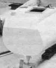 not really radically changed for a number of years. The bottom of the craft is round. This shape supports the most weight for the least whetted-surface area. There are advantages to other shapes, but the basic form begins with the ‘U’. It can be flattened at the bottom towards the rear of the craft to give more buoyant lift and to encourage planing under certain conditions. Internally, the space will be restricted if the sides above the round bottom of the hull remain vertical or even have some tumblehome to reduce windage. This was the way that Toria, Kelsall’s first real racing trimaran was constructed Toria's round-bottomed transom detail, boat under construction
Beam shelves
 To gain internal space, trimarans must have platforms extending on either side of the mainhull. These are the beam shelves (see picture left from D H Clarke's Trimarans of a Nimble-class craft). In a structural sense they add great stiffness to the gunwale area. The beam shelves are usually used for bunks in most trimaran designs. This was the style used in the first 'western' trimarans designed and popularised by Arthur Piver who crossed the Atlantic in his plywood 30ft Nimble in 1960. His hulls were more flaired ‘V’ shaped, that is, they angled outwards above the waterline to produce more internal volume. This design was the basis for cruising craft for a number of years. If the two concepts ‘U’ & ‘V’ are combined, an improved basic shape to produce internal volume becomes apparent.
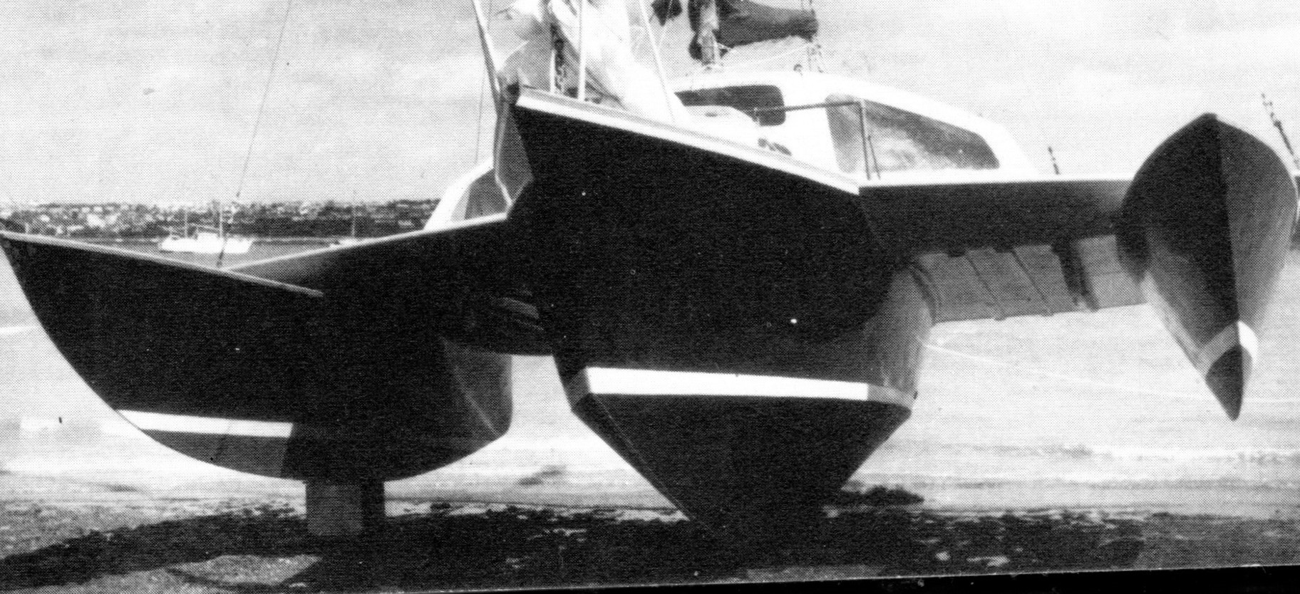
 The line of join between the two forms can also be curved outward in a flaired knuckle to further improve the shape. The knuckle is minimal at the bow, but increases as it goes aft. This allows for another increase in volume above the waterline. On flat water there is little immersed hull area, but in rougher conditions the craft quickly picks up more buoyancy as the hull is more deeply submerged onto its area of greater volume. The area of the knuckle can also provide dynamic lift. Right. Waterline at bottom of transom. Flaired knuckle, beam shelf at top.
Length. The link between length and potential speed is well known. To take advantage of this, the craft has to be as long as possible for any given weight.
Craft development and the Evolution of materials
 We can look at the dimensions of 1. A traditional timber boat. 2. An early GRP cruiser to make some useful comparisons with the craft that I am about to describe. Although these craft were for a different purpose, they were not regarded as particularly large and, some of their dimensions might be roughly comparable with my boat which will illustrate how radical a trimaran can be. We can note some terminology which will become relevant later.
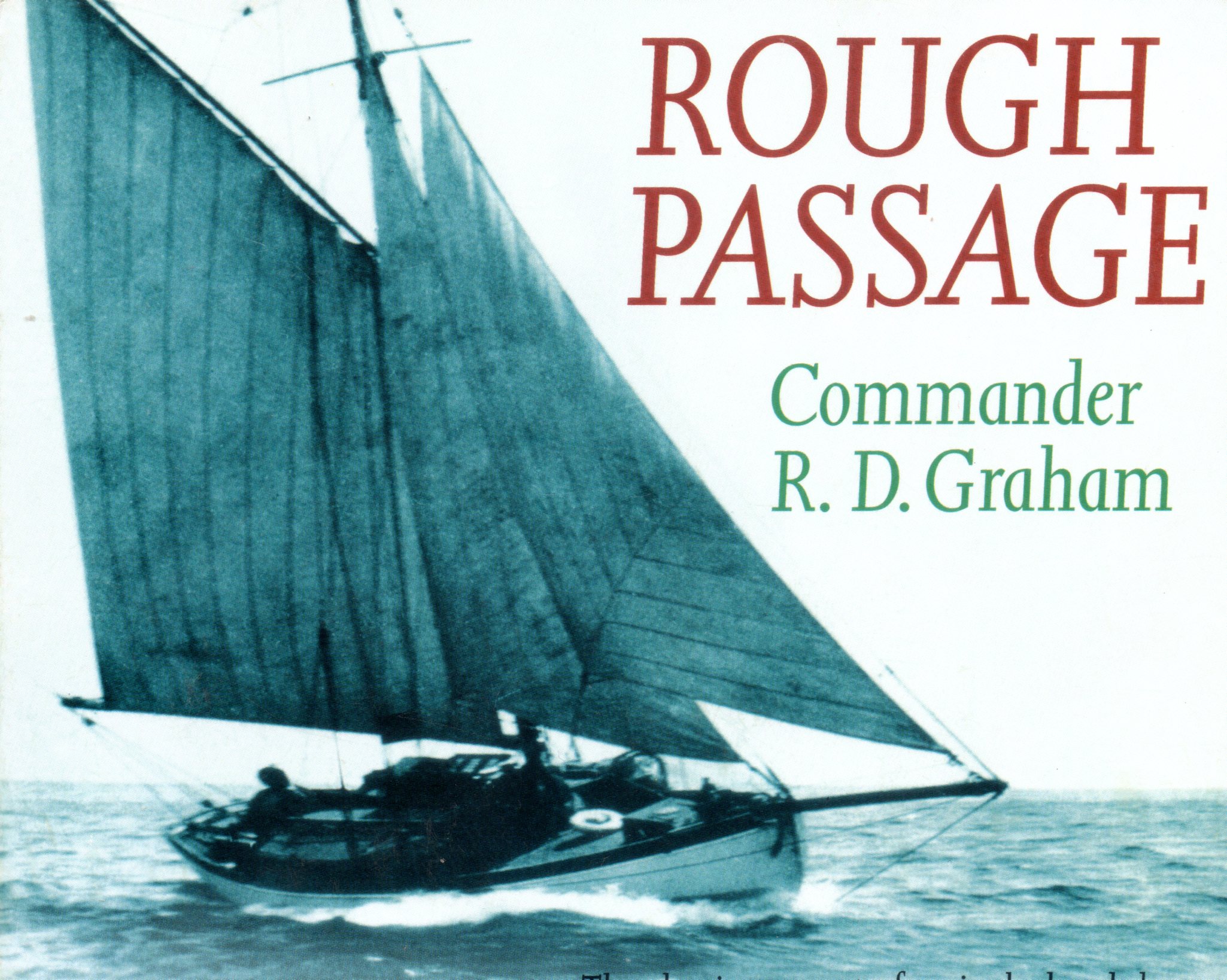
Wood. Taking an example from the days of wooden craft, we can look at a cruise account in a book called Rough Passage (Seafarer Books and Sheridan House) by a man called Commander R.D. Graham. He cruised singlehanded across the Atlantic to Labrador, Bermuda and then returned via the Azores in the early 1930s. He had a very traditional, long keel, wooden, gaff cutter, Emanuel, that was 30ft LOA, by 8’-6” beam, a draft of 5ft, LWL of 25ft. Ballast 3½ tons, Craft weight over 7 tons. Headroom was 5’- 4”. The bowsprit would not be included in the LOA. Different organisations/nationalities have different approaches to including bowsprits within LOA. There are many references to this wooden boat being small, but the 30ft length would be the stem-to-stern hull length as this dimension would be on any builder's plate attached to the vessel. The bowsprit would produce additional length.
Hull 30ft long - 25ft on the waterline - displacement 7 tons. (See this boat on website: yacht-emanuel.co.uk)
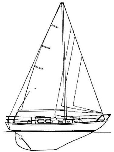 Fibreglass. It is interesting to see if we go back to the early days of GRP that, for example, the Nicholson 32 designed for cruising in 1962/3 has an outstanding pedigree and an impeccable reputation as a cruiser. It is a classic design. It has been described as a 'pioneer of GRP construction' and 'one of the best yachts ever made'. In racing, a number of ‘Rules’ intended to produce fair racing, influenced the shape of yachts, this could apply to the Nicholson which is sometimes described as a cruiser/racer. Its Length Overall (LOA) is 33 feet. This will be the hull length as it did not carry a bowsprit. The Waterline Length (LWL) is only 24ft. This reduction in length must have a marked effect on internal volume as well as performance compared with modern craft and was probably the result of a racing-rule influence. Boats with overhanging ends pick up length as they heel. The design makes up for loss of internal volume with the Beam 9'-3". Draught 5'-6", Displacement 6 tons of which Ballast 3 tons.
Hull 32ft long - 24ft on the waterline - displacement 6 tons. (See this boat on website: Nicholson32.org.uk)
My boat. The all-up dimensions of my craft are LOA 25, LWL 23' - 9" (static, see rudder details as it can change when dynamic), craft beam 17ft, mainhull beam 8ft, mainhull waterline beam 3ft, headroom 5’-11”, draft 2ft, draft max.daggerboard 5ft, craft weight in cruising trim about 1¼ tons. As will be seen, modern trimarans do use bowsprits, but they are usually made to fold.
Hull 25ft long - 23'- 9" on the static waterline - displacement 1¼ tons. (See the notes on static waterline, under Rudder)
It is worth repeating that these boats are very different, but in places their statistics are similar. My boat has not crossed the Atlantic or girdled the globe, but putting their dimensions together emphasises some of the radical changes due to their materials and sailing concepts. The greatest difference is Weight. An interesting dimension is waterline length (LWL) compared with overall length (LOA).
Wood Early Solid GRP Foam Sandwich GRP Tri
Length Over-All 30 32/33 25
LWL (Waterline) 25 24 23'-9 or 25'-9
Beam 8'-6 9'-3 3ft or 8ft or 17ft
Weight 7 tons 6 tons 1¼ tons
Min/Max Draft 5ft 5'-5 2ft or 5ft
Headroom 5'-4 6ft 5'-11
Bow Shape
25ft feet is very short and so, I sought to maximise this where I could. The rake of the bow is the first obvious place. It should be vertical for maximum length. The more angled it is, the shorter the boat becomes on the waterline. The aesthetic choice for me was not to have a plumb bow, but to reduce the visible angle as much as possible, but then as the stem approached the water, to make it vertical. How much difference did this make? I gained a few inches, but this is how designs are maximised. Possibly, if I was to start again today, I would have a vertical bow, but there are advantages for cruising boats to have an angled bow. This is particular so when mooring or anchoring to keep the ground tackle away from a finely shaped part of the hull, so it is not a forgone decision.
Stern shape.
The other end of the boat is another opportunity to maximise length. There are some factors to consider. I have often read about owners adding a ‘sugar scoop’ to their transoms. It seems that dragging transoms are not unusual in cruising boats and they will slow the boat if this is the case. Why didn’t the designer of such craft see this in the first place? What is going on here? Without going into too much detail it probably relates to the waves formed by a craft as it passes through the water. A displacement craft will move its own weight of water aside, to move forward its own length (Archimedes). At increased hull-speed for the boat, it produces a wave at the front and then a long trough followed by a wave at the back. The rising wave at the stern can swamp the transom. It is possible to extend the hull above the water to allow for this action, which is partly the reason for LOA being greater than the LWL as already mentioned. Adding a sugar scoop has this extending effect, but makes the boat longer. I decided to make my 'sugar scoop' part of the rudder. The boat is 25ft long, but the rudder is transom-hung and technically not part of the length measurement. This extension turned out to be a bit of a challenge, but I did manage it and the explanation will be part of the section relating to the rudder. Extending the waterline length to gain speed has always been important, especially with slender hulls, which this boat has.
Rocker. As I would be sailing in a narrow river and tacking through moored craft, I wanted the 17ft-wide boat to turn quickly, so I made sure that it had a rockered keel. This simply means that it had a curved shape when viewed from the side and was not immersed to an even depth right along the length of the hull. Having a lot of rocker can result in an over-responsive boat that needs steering all the time to stop it going off course. I found that I could have a normally responsive craft and I could also make the boat lock on-course and feel like a longer boat by using my boards, whilst still having the manoeuvrability of the rocker, which is dealt with below.
Lateral resistance
This is very important, for it can be shown mathematically that windward ability is greatly produced by the lateral resistance of the hull to the water. There are other factors such as speed and shape. In general, the power/weight ratio means that for any amount of input power, the lighter-the-weight that the power is pushing forwards, the bigger the gain in performance. Lightness is where the multihulls can make substantial gains on their ballast-carrying alternatives. In general terms, do most yacht owners understand how much ballast their craft is carrying? For cruising craft of about 30ft, it could be the equivalent of a small family car and historically, much more (see Emanuel above). The ballast can have performance advantages when used as an energy store, but that is an allied issue. It is potentially one factor for ballasted boats ability to windward.
The stiffness of the craft is very important in energy gathering. As a boat heels, it presents less energy-gathering sail to the wind. To some extent, a cruising yacht will have a limit on how much power it can extract from the wind, set by its stiffness. Ballasted monohulls use this automatic, self-adjusting-sail-area system (heeling) to stay upright. To do this they carry the same ballast at all times. Trimarans, being stiffer, favour a different priority. Their sail area changes little, but they have an automatic-self-adjusting-ballast system instead. I like the way that a trimaran effectively ‘adjusts ballast’ automatically using the bubble-&-stick principle. The righting ‘ballast’ is provided by a ‘bubble’ (float) that effectively constantly changes size depending on how much righting moment it has to apply to the craft. It is on the end of a stick (crossbeam) to give it leverage. In very light wind it provides next to no ‘ballast’ to keep the boat upright, as it does not touch the water. The wind begins to blow and the float (bubble) is pushed into the water exactly the right amount to resist the sail pressure. A gust hits and suddenly a lot of ‘ballast’ is needed and exactly the right amount is delivered. The buoyancy (ballast) comes and goes in a constant cycle precisely measured to counterbalance the sail pressure at any given moment. It is satisfyingly neat.
Windward ability greatly depends on windspeed, angle to the wind, stiffness, power/weight – and - lateral resistance relating to hull form. A well-heeled monohull will have an underwater shape hardly relating in any way to the designer's original drawing of a vertical craft.. The imbalance of the immersed hull form is what increases weather helm and in extreme cases downwind, will cause the craft to broach. Limiting the heel in a trimaran means that the immersed hull shapes remain closer to those designed to be sailed on. Immersing the leeward float going to windward will increase the chances of the craft behaving like the monohull and rounding-up, which might be regarded as a safety precaution. The designer Dr Harrison-Butler spent a great deal of time addressing this problem for monohulls and produced the 'Metacentric Shelf Formula' to try to improve performance. Modern monohulls have increased beam to try to resist heeling and retain their designed hull form for longer, as the wind speed increases.
Balance. When the power is applied to the hull the whole set of forces start to operate in ways that it is difficult to quantify and understand. Text books will begin to give outline explanations, but they often use static models to explain dynamic situations. Cardboard patterns of underwater shapes are poised on knife edges to show how hull balance can be achieved. Sails have geometric lines drawn to find a centre of effort, which then has to be placed correctly in relation to the centre of lateral resistance. Does it work? Well, from my observations – not always. I have read many accounts of boats that when launched, did not behave as their designers predicted and their owners expected, resulting in expensive modifications. I look at cat-rigged boats with their masts set well forward and I wonder about the geometric lines on the sail. I wonder about the effects of fullness and flatness of the sail in directing drive. I look at a number of traditional long-keel monohulls such as the well-proven Nicholson above, that have clearly deeper hulls towards the stern than at the forefoot and I wonder, again, about the knife-edge balance which can be totally transformed when attaching the ballast. Then, when the situation becomes dynamic, everything is more complex than text-book cardboard shapes can show. I think that the people who drew the Nicholson had more experience than to rely solely on balanced cardboard alone. They did a good job.
There are some simple ways to think of lateral resistance. Put a hull into the water, push it in the middle of the side and it moves away. Drop a daggerboard near the bow and push the hull in the middle – the stern will move away more than the bow, because the bow is ‘anchored’ to the water by the resistance of the board. Move the board to the stern instead of the bow and push in the middle again – the bow moves away. It’s basic and it’s obvious. The Polynesians crossed the ocean without using rudders. Ok, they had sweeps, but they also used daggerboards to get the initial balance and direction correct. Dinghy sailors move their weight forwards to increase bow lateral-resistance going to windward and then they move back to encourage downwind steering and stability. I recall many years ago, going as an observer to the start of a Round-the-World race where large monohulls began their epic downwind voyage. All the boats were optimised by design, for going to windward. I wondered at the wisdom of this. Why would anybody do that? Shouldn’t they have the option of changing the lateral resistance of their hulls to make the steering easier?
Foils (Boards)
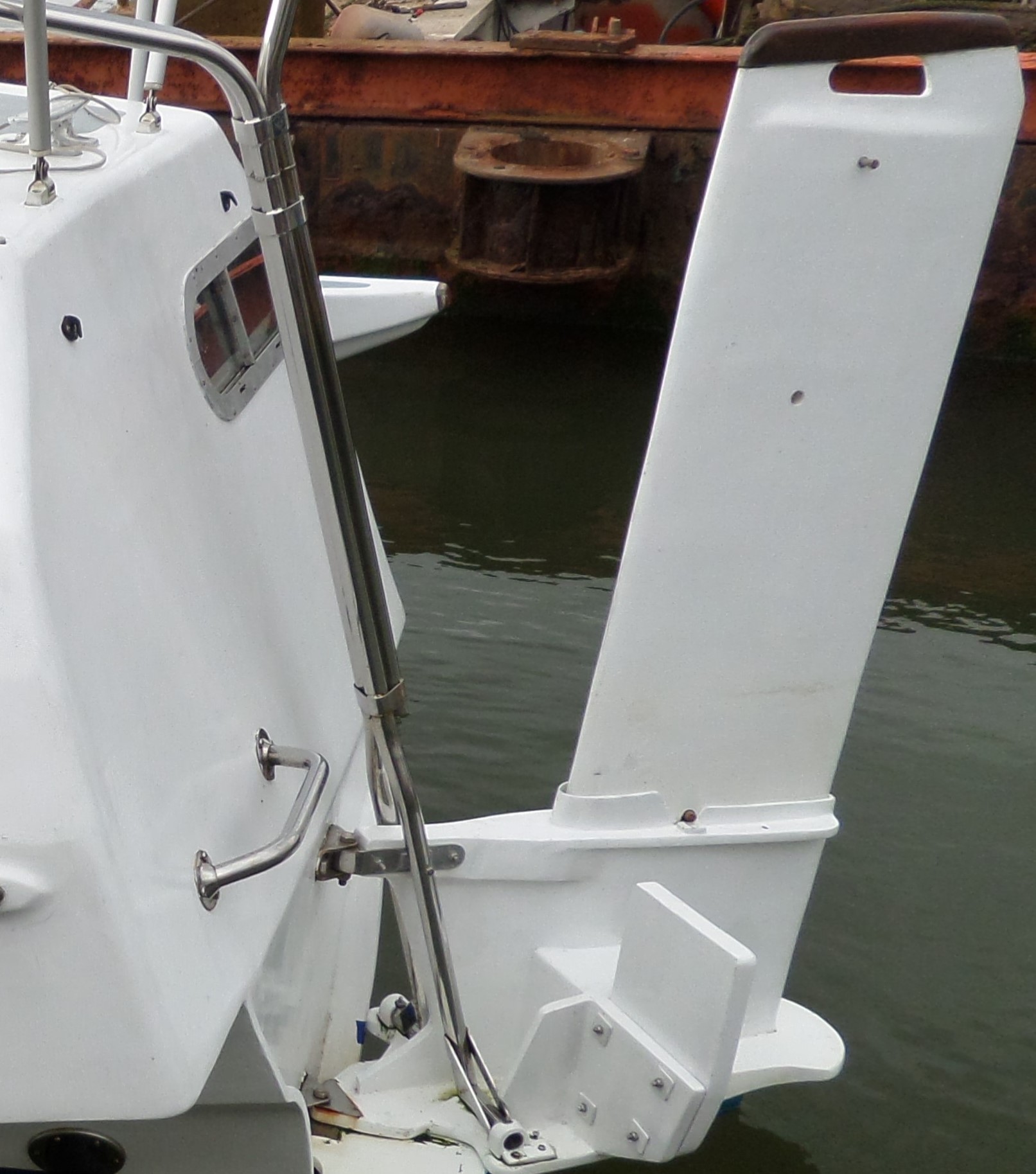
My 25ft trimaran has two daggerboards. The Main one (centre below) is forward and the aft one is called a Trim-board (right of picture), because it is used to adjust the lateral resistance of the boat in different conditions. The main board (centre) is large (600mm wide) and the trim board (450 mm wide, 6.3kg) is smaller. When the mainboard is down 550mm the boat sails and steers quite normally. It can often be further submerged to 700 and 800mm for windward work. The 900mm depth is rarely used (see below). Both of these foils are 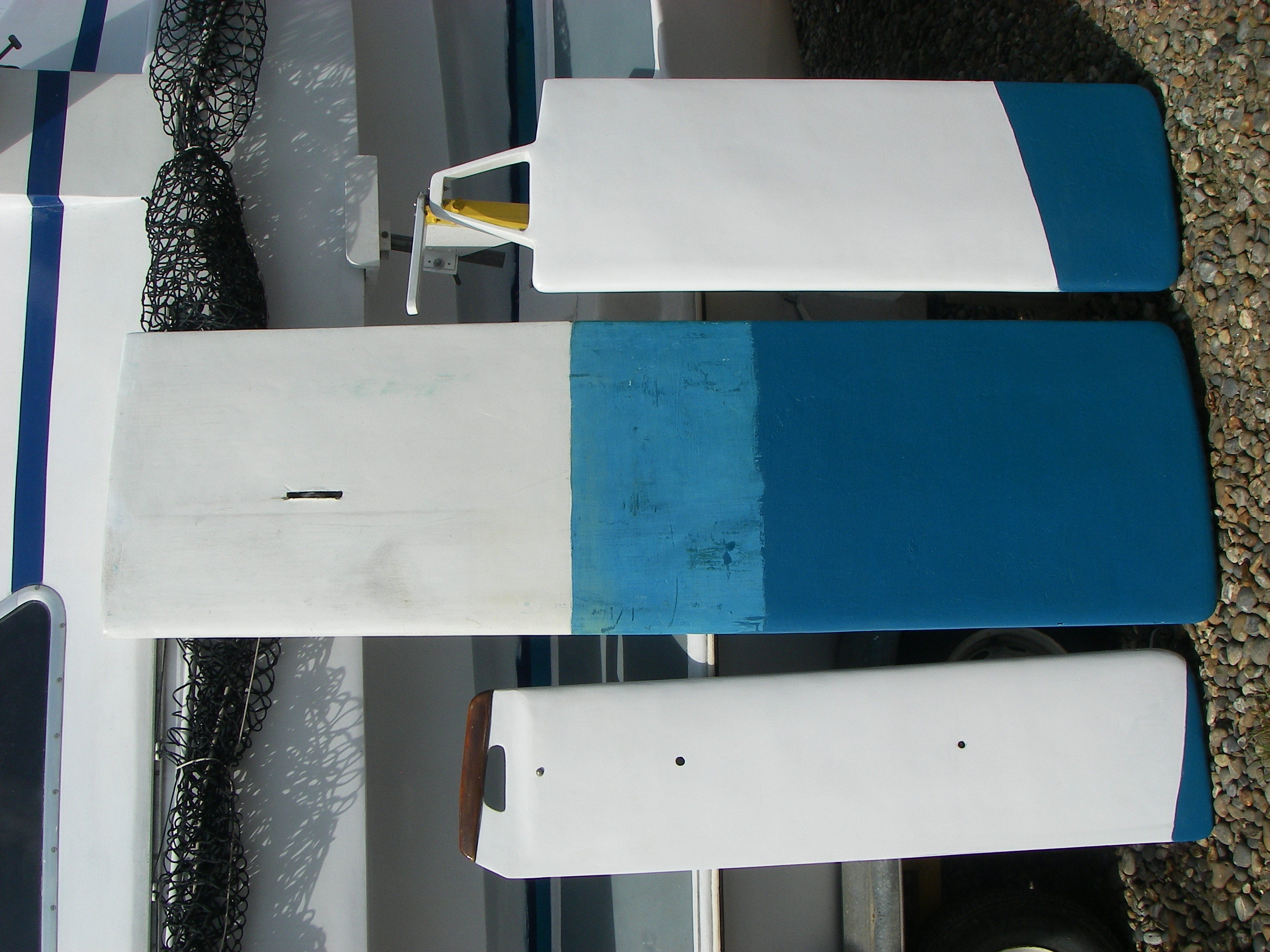 hollow and, in use, they have to be pushed down. To lift them, it is simply a matter of releasing them and they will lift themselves. The rudder (left of picture) also is an important foil when it comes to lateral resistance and this too is a daggerboard, so there is plenty of scope for all adjustments. A hole at 390mm from the base keeps it clear of the water. Another hole at 970mm gives it the usual operational depth, level with bottom of the hull. Dropping it to the 1230mm retaining bolt is rarely used The solid rudder (360 wide, 9.7kg) is heavier than the trim board and will automatically drop when it is released from its stock (7.9kg).
In light wind, going to windward, the main board alone is sufficient, but as the wind increases the trim board is used to reduce the weather helm being felt through the tiller as the float begins to submerge. It has a remarkable effect. Without it the rudder would have to be over-steered as the float grips the water and it would be overloaded. The trim board alters the characteristics of the boat. It can be deployed alone off-the-wind to move the lateral resistance back, when the main board is raised. Sailing downwind, with the main board up and the trim board down, any tendency for the boat to round-up in heavy gusts is reduced. Having two boards has another effect that I mentioned when referring to rocker. If I have to tack through moored craft, I do not set the trim-board. The boat remains very manoeuvrable and will go-about instantly. On a straighter sail I don’t want her to feel short and less steady on course. I want her to feel longer, slower to wander and steady on course. This is achieved with the trim-board. It is possible to get caught out after a long downwind sail using the trim-board only. The boat has to be rounded up to drop the sail and she can be reluctant to luff without the main board down. Flip the trim-board lock off and it lifts itself. Push the main-board down and the boat will turn easily towards the wind. It is a reminder of the effectiveness of the system.
Offset. Both boards are offset so as not to pass through the bottom of the boat. The hull has a grounding skeg that is NACA section to protect its bottom. The main board is close to one side of it. My choice of offsetting the board came from Tony Smith’s 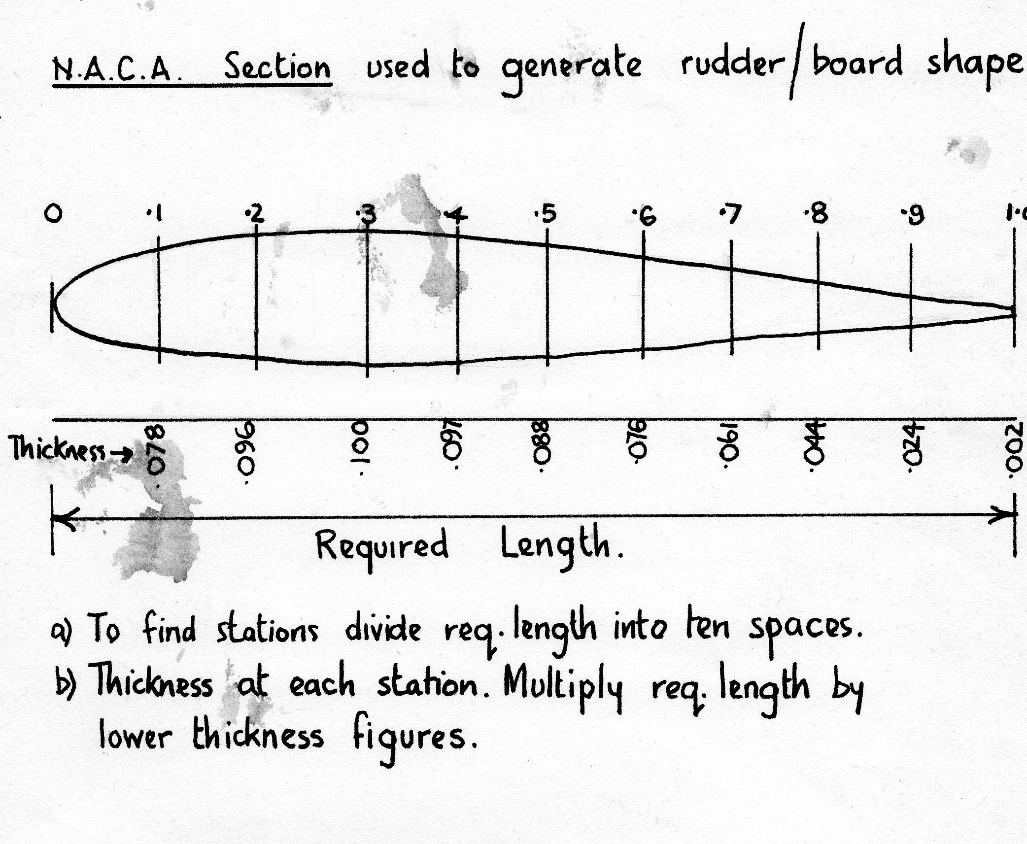 Telstar. He pointed out that it doesn’t really matter where, across the hull, the board is positioned, but if it is at the bottom it will pick up stones to jam the board when aground. If it is on the curving section of the hull, both sides of the exit slot are not precisely opposite to each other. One edge is higher than the other and this reduces the possibility of jamming. The trim-board exit slot is elevated above the bottom of the boat towards the stern and so, does not pick up stones. As all boards can be raised, they leave the bottom of the boat without projections other than the protective grounding skeg. This is useful when on a mooring in a tideway and for freeing warps should they become caught.
Both boards are lifted and lowered vertically, they are not raked. The rudder is raked forwards as it descends - more of this, when it is described. It is made from encapsulated plywood, so it is comparatively heavy and automatically slides down. I don't want it accidently popping up when sailing. Plywood is good for making the core of boards as the different layers give an indication of how much wood has been removed when shaping. This is especially so if the grain is aligned vertical/horizontal, but - Beware! If the strength of the plywood is to be used, then the grain should be aligned at 45° to vertical. Vertical/horizontal grain aligns only half of the wood fibres in the correct vertical direction, so the wood's strength is only half of the apparent timber thickness. It is better to rely on the encapsulating glassfibre for the strength needed. U.D.W.R. (see Part 3, GRP Flat Table) glass should be used vertically and it can be increased in thickness as the load increases towards the top of the board. I have included the weight of the hollow trim board and the smaller solid rudder (above) for comparison. They are all NACA sections and I include the rough note I used about the proportions to be used for such sections.
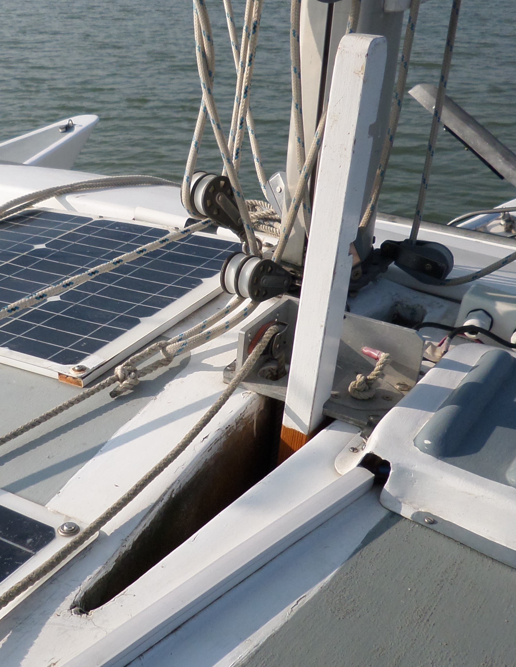 The hollow Main & Trim boards naturally float up and therefore they need to be pushed down to deploy them. If they touch bottom or hook a line they need to be lifted quickly. They were constructed on an internal skeleton and skinned with solid glass sheets made on the flat table. Once their form was established they then had their strong external skins applied and skimmed. It takes some force to push the main board down beyond a certain point, as effectively, it is like trying to lift the mainhull higher in the water. The board is held down with a simple stick with notches in the front edge at different point (see right), that engages with a metal pulley-plate on deck. A lifting line passes through a pulley in the board to assist in lifting if needed and to secure the board up, when not afloat.
All boards had to be constructed first in order to act as the basic pattern for their boxes. To make a box, something of a uniform thickness can first be applied to the board; winding thin rope around it can work. Flat solid glass, or glassed-one-side, foam sandwich sheets, smooth side inwards, can be used as the foundation of the boxes. These boxes can then be strengthened by more glass externally. They will be further stiffened by glassing them into the structure of the boat.
Rudder
 The rudder operates in broken water and is surface-piercing. In waves it will be pitching up and down. The upper third of the immersed blade may not have maximum effect. Rudders are more effective when they are operating in solid water, underneath the boat. I invested a great deal of effort in trying to make this possible, whilst still retaining the advantages of having a transom-hung rudder. One quality that is most prized is the ability to lift the rudder from the water in case it should be fouled by something. A small racing catamaran design called Firebird hinged the whole of the rear of its hulls to allow them to rotate upwards to lift the rudders from the water and this idea has been used elsewhere.
Multihull rudders are highly loaded due to additional speed potential and also, because in the trimaran they can be steering the bow of the float that it offset to the side of the craft. Conventional pivoting ‘dinghy-style’ rudders cannot be relied upon to stay down. If they use elastic in their downhaul systems they are impossible to keep down. The water pressure will force them backwards which increases the leverage and the load upon them, whilst decreasing their effectiveness. The only way to keep them down is to lock them with a sacrificial peg. They are then, effectively, solid when sailing. Daggerboards are the best solution for multihulls as they can be lifted clear of the water on moorings and to clear obstructions. I prefer my rudder blade to be angled forwards as this sets up the waterflow across the board. If a board is angled backwards the water will flow off it downwards as it crosses the board. Angling it forwards lifts the water into the aerated zone at the top of the blade, making more blade operate in more solid water. Angling forwards puts some blade forward of the pivot axis, thus balancing the blade to improve its power. If the blade should touch bottom at slow speed, there is a chance of it being pushed upwards to relieve the shock and make it more possible to recover it.
The holes in the rudder take an aluminium-tube peg that is secured to the top of the blade with a lanyard. The lowest hole locks the rudder completely clear of the water. The next hole locks the rudder at the same depth as the bottom of the hull, so the rudder is not the deepest part of the craft. At the top of the blade is an extended bolt with tube spacers. This stops the board from dropping right through and falling out of the bottom of the stock, although that would not easily happen as the board picks up a little buoyancy as it is more deeply immersed. The blade can be dropped to this stop to give even greater lateral resistance and act as the trim board does, bringing the boat balance further aft and reducing weather-helm.
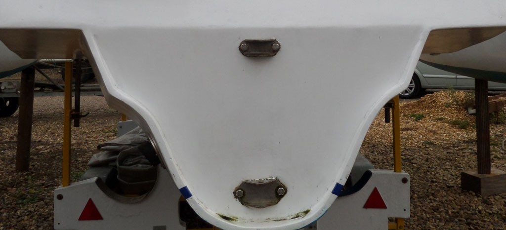
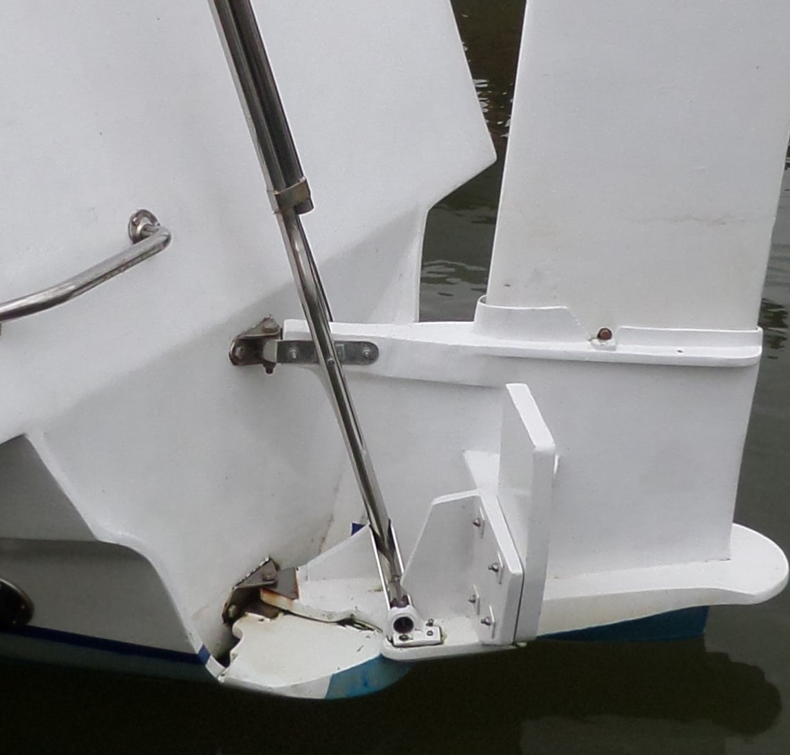 Rudder Stock. The rudder blade is secured within a stock to which the tiller is attached. The underside of this stock can be shaped to provide a ‘fence’ for the foil, to stop the water beneath it from lifting further. It is like an extension to the bottom of the boat. In fact, in this craft it was made as part of the bottom of the hull and then cut off to be modified to take the rudder passing through it. This is the practical use of the 'sugar-scoop' extension that allows the boat to sail on an extended waterline length. The pictures show that it is also possible to use an outboard on the rudder stock in an emergency.
Stock Shaping. An extended sugar-scoop-shaped rudder stock will not rotate against the transom as its flat, front edge will press against the back of the boat, so it will have to be cut away to at least 45° on either side of the pivot to allow turning Packer ahead of rudder movement, this creates a gap between the rudder and hull. To overcome this problem the bottom of 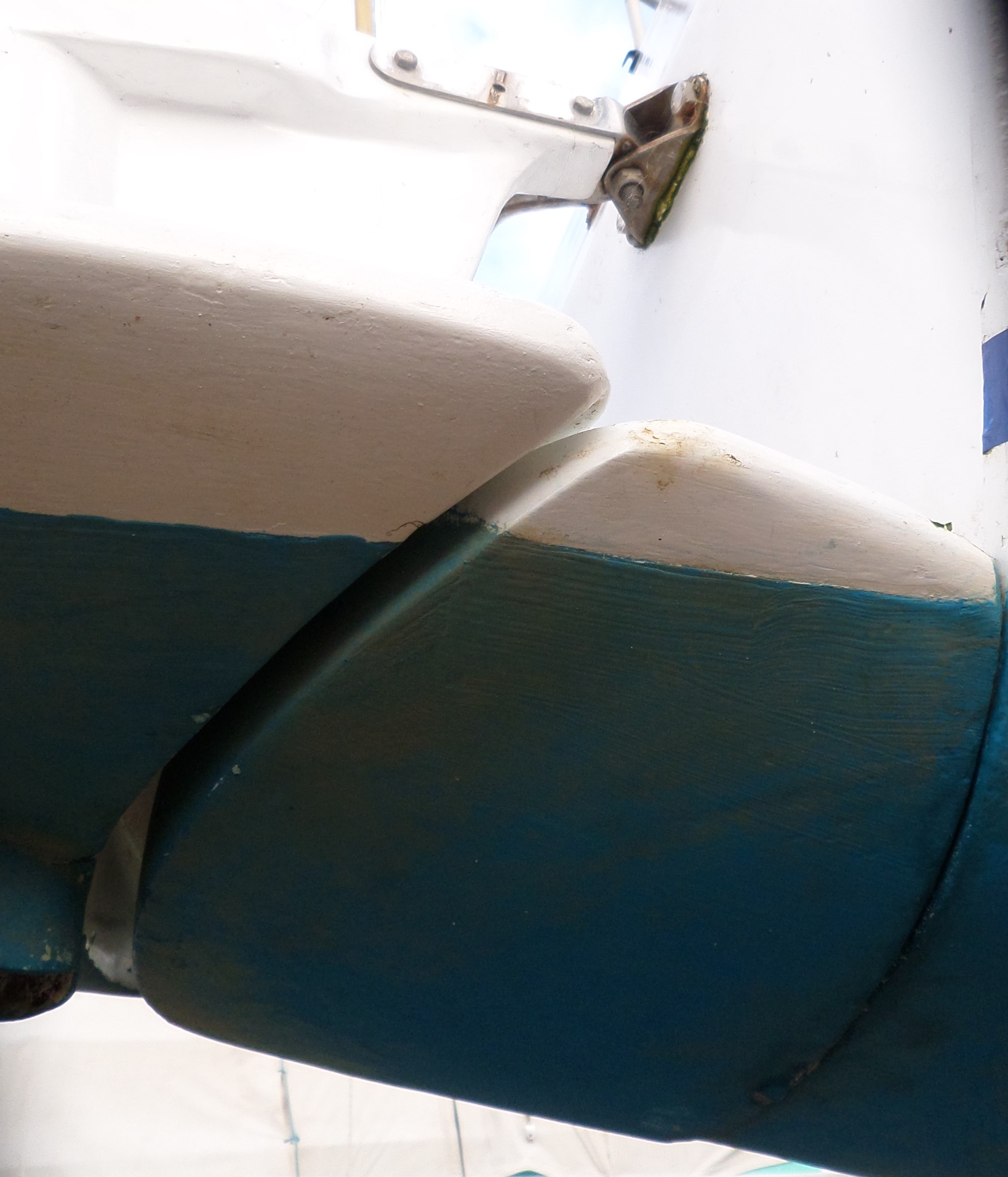 the stock was cut into two component parts. The section against the transom that might be called a ‘packer’ is straight across at its front edge, but has a semi-circular shape to the back. The component holding the rudder has a matching semi-circular shape at its front, to allow it to rotate around the packer. The gudgeon/pintle pivoting fixings that attach the extended rudder-stock to the transom secures both components in place. The rudder does not rotate directly against the transom, but describes a small arc of circle around the packer. This small change in its action from the normal rudder movement does not seem to make any difference in the steering. There is a smooth transition of the hull through to the rudder without large gaps and the rudder is operating below the extended stern of the boat. If LOA was not important the curved packer could be included as an extension to the main hull. At rest and in light conditions, the whole of this stock section is clear of the water with minimum whetted surface area. When the boat makes the normal displacement wave-pattern, the water is lifted to increase the operational waterline length of the boat by about 2ft making the operational Waterline Length 25'- 9" on a 25ft boat. It is a similar principle to using the extended overhangs on the old, early racing monohulls.
Tiller
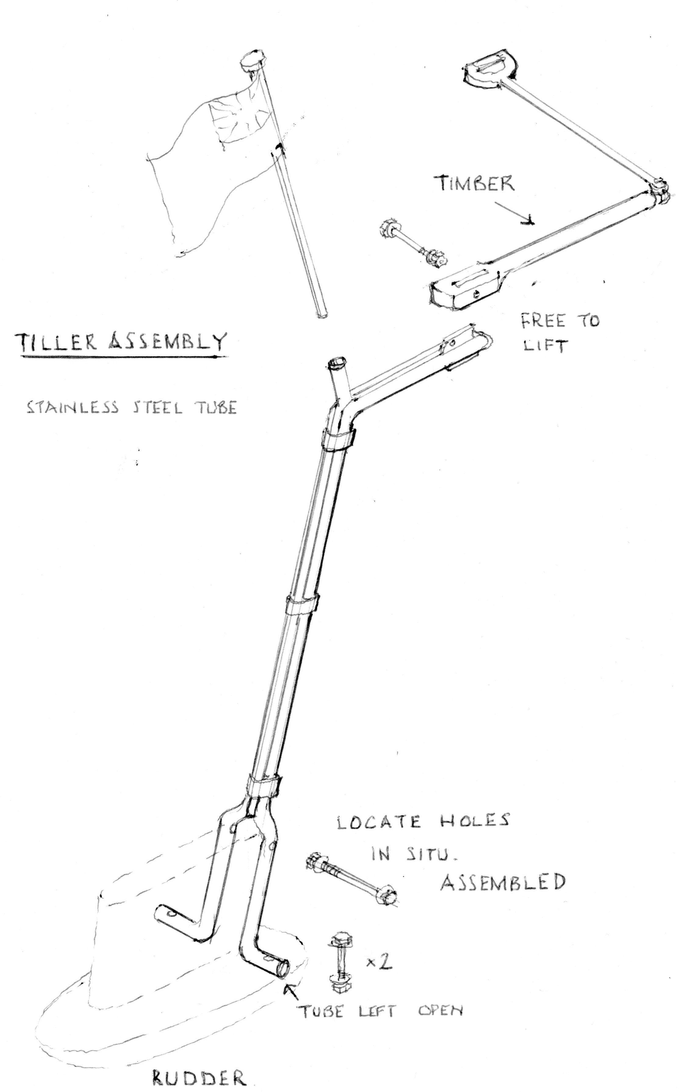 My previous boat had wheel steering from a sheltered internal position. I liked it as it used a very simple system of terylene lines around pulley blocks onto a short tiller. It was ‘invented’ in a hurry, but worked permanently and with no maintenance for the life of the boat. There wasn’t the space to repeat the system on this boat, despite several trials, so in the end a tiller system was used (see early sketch). The tiller had to come up the stern of the craft, then across the aft deck, which was a potential problem with the aft-cabin access hatch. To make the arrangement stiff enough, the vertical component of the tiller is made up of three stainless-steel tubes attached to each other. Two of the tubes branch either side of the rudder stock and are secured to it at the bottom. The third one is bent backwards at the top to hold the ensign staff. The mini-ensign is a modified courtesy flag. The curving, single, stainless tube (not wood as in the sketch) tiller handle is pivoted, so that it can be lifted and it also has a tiller extension in case it is needed. When not in use the tiller is clipped to the port, pushpit rail which keeps it clear of the aft-cabin hatch. Steering can be done from the low cockpit-seating position, which is more protected, or from the higher coaming which gives good all-round visibility.
Cabin/Cockpit/Deck
The heaviest objects loaded aboard a boat are the people. A heavy man might weigh 100kgs and a light woman could be down to 50kgs. To keep the maths simple, take two couples and combine them at 300kgs total. That is a lot of weight to be sitting near the transom in the conventional aft-cockpit position. The shorter and lighter the boat, the more telling this will be, for it is an unchanged load, immaterial of boat size. The weight of people is a higher proportion of the overall boat weight the smaller and lighter the boat becomes (e.g. Nicholson 32 at 6 tons, or this boat at 1¼ tons). Could this be another factor in the need for a sugar scoop on small cruisers? One solution to this problem is not to sit these people at the back of the boat, but to move them and therefore the cockpit, closer to the centre of the boat.
This reasoning also applies to another heavy lump. Don’t have an outboard on the stern, bring it forwards, alongside the centre cockpit. If you are using an inboard, then it will already be further forward in order to gain the space for the stern gear - propshaft and propellor. It will be lower down for better stability.
After this, the next heaviest load will be water. More of this later. The anchor and ground tackle are very heavy and if they can be stored further inboard than at the bow, that would be desirable. I failed in this, as I found it easiest to place them just behind the bow in a dedicated anchor well, that also gave me a strong securing point for the forestay, below the deck level. Having the anchor there means that it is available if it should be needed in a hurry. Lighter-weight anchors are now available.
Internal Arrangements
For this cruising craft, so far, the design intention had been to maximise sailing efficiency. Now, the effort must be to provide sufficient living space for the crew. This will be dealt with in more detail later, but this is the outline. Designing for a family of two adults and two children, an aft cabin provides the space for the children. Children having their own cabin space is very popular. The engine, with some storage over it, occupies some space low down, below the cockpit. The main cabin forward of the cockpit provides the space for the galley and general accommodation. It has full, standing headroom in the main cabin. Forward of this is sleeping for two adults. Portable ‘camping’ toilets are provided for the adults forward, and at the stern for the children. It is possible to move from the aft cabin to the main cabin inside the boat, sliding below one side of the cockpit. There are entrance hatches for the aft cabin, the main cabin and overhead, in the fore cabin.
On deck, most monohulls will have small side-decks either side of the main cabin. They restrict headroom below at the sides of the boat. The trimaran does not need these, as there is an area outside the hull, from forward beam to aft beam that can be used as a walkway. This allows the cabin sides to extend out to the full hull width, creating much more internal space. Viewing the centre section of the main hull from the deck, it is 8ft wide. With standing headroom inside the cabin, the boat at head height is still 8ft wide and it is not noticed that the waterline width is only 3ft. This arrangement also determines much of the layout of the deck.
Modern trimarans
Most trimarans deliver 'performance' as their primary quality and it is worth noting that there have been many developments, often through the influence of racing, since I constructed mine. Smaller-sized craft up to about 35ft may fold, so that they can enter 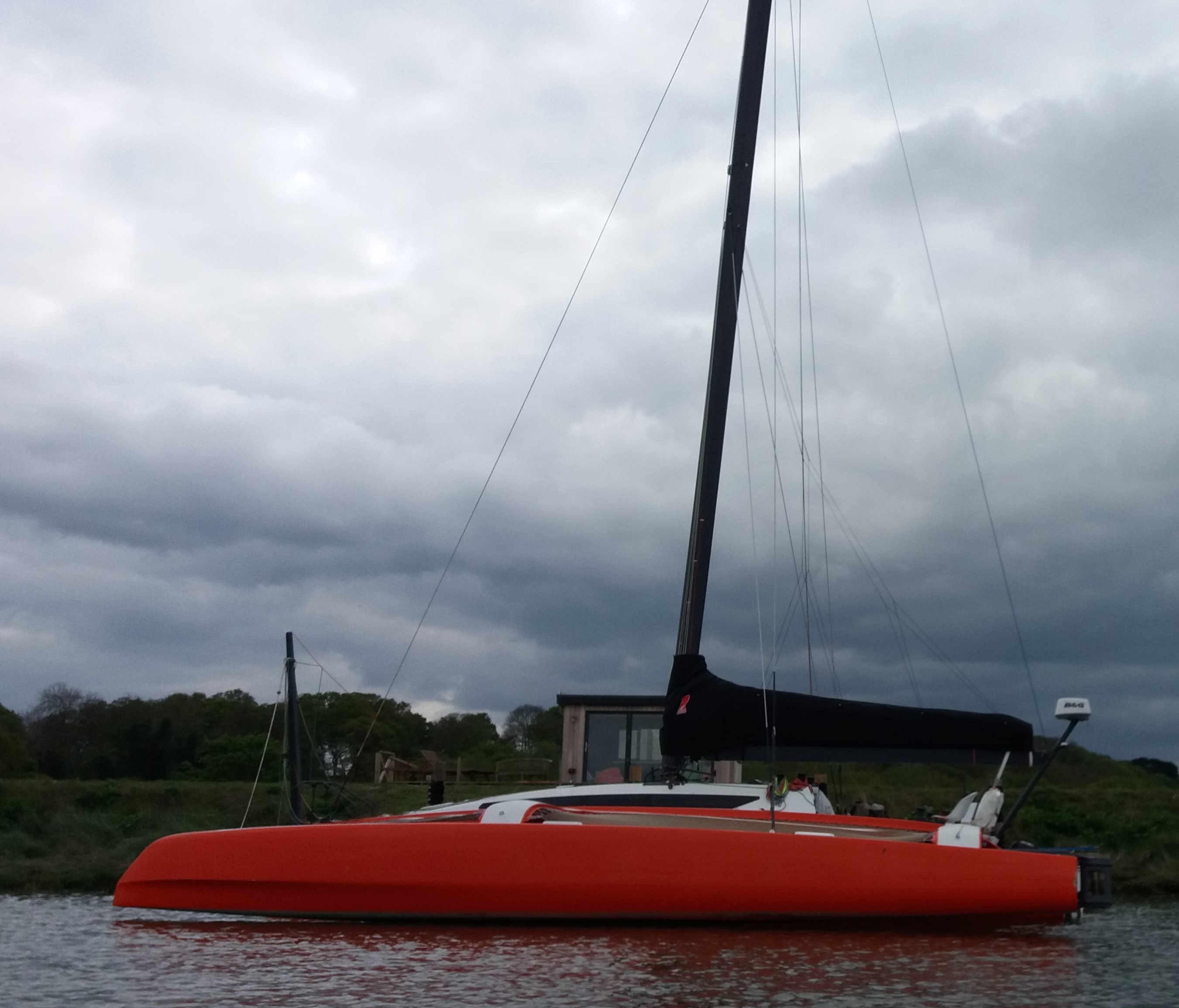 marinas. If the floats rotate backwards the craft will be longer in the berth and may have to pay more. If the floats rotate downwards, there may be issues with keeping the outside of the floats clean. Only the Telstar 28 rotates its floats inwards, whilst still keeping them upright and without extending the length. Larger racers up to about 40ft can be demountable like mine. This is so that they can fit in shipping containers to be transported. Mine fits on its trailer for road transfer. 32ft Orange Tri called Freshly Squeezed
Larger craft will have big daggerboards and rudders on the stern of the floats in addition to the main rudder, for the mainhull rudder may become aerated when the craft is pressed and the mainhull begins to lift from the water. Even-larger craft may use lifting foils in addition to the floats. There will be mainhull daggerboards. A rotating mast will be set well back, to place as much of the buoyant lifting power of the combined mainhull and float, ahead of it. The mast will be raked backwards to direct the sail force in such a way as not to depress the relevant float bow. Floats may have 'destroyer' bows. The overall beam will be great, some craft can be square and the floats will be canted outwards, so that they become vertical when pressed into the water.
The biggest changes have been in materials used. Carbon fibre in hulls and rig have reduced weight whilst increasing strength. A 30-35ft craft can weigh in at about 3 tons, which is less than the ballast on the similar-sized timber cruiser from the 1930s. Speeds of around 30 knots can be produced by 35ft craft. Mainsails are fully battened, with laminated sail materials, moulded to shape. There will be a range of sails including light-weather, top-down furlers, set on bowsprits. Engines will be outboards to save weight. Foils lift the boats clear of the water. There will be no internal trim on dedicated racers - just the bare carbon. On the biggest round-the-globe racers the crew now rarely go on deck, but monitor the craft from inside.
Minimum food, minimum water, minimum cooking, minimum comfort, minimum sleep.
My boat does not fall into these categories.